ENERGY_PERFORMANCE_ASSESSMENT_FOR_EQUIPMENT_AND_UTILITY_SYSTEMS_(CHAPTER-16:ENERGY PERFORMANCE ASSESSMENT OF PULP & PAPER INDUSTRY)


ENERGY PERFORMANCE ASSESSMENT FOR EQUIPMENT B AND UTILITY SYSTEMS

(CHAPTER-16:ENERGY PERFORMANCE ASSESSMENT OF PULP & PAPER INDUSTRY)

Introduction

Paper is produced from cellulose pulp fibers, derived from wood, rags, agricultural residues like bagasse and wheat straw or from waste paper after drying on a battery of steam heated dryers. Paper is a versatile material and finds many uses in our daily life. Traditionally the most common use of paper is for writing and printing, but it also finds various applications as a packaging material, and for large number of industrial and construction processes.

Historically the first use of paper is recorded in ancient Egypt civilisation as a thin paper-like material made from the pith of the papyrus plant, a wetland sedge, grown in the Nile Delta of Egypt. The name paper has therefore originated from the word papyrus. However, the development of pulp and paper making process dates back to 105 AD in China. Over the years, process and technology for paper manufacture has progressed steadily and today in the modern world, paper has linked with cultural and industrial developments. The per capita consumption of paper is often considered as a yardstick of development. The per capita consumption of India stands at only 10.8 kg as against 42 kg in China, 22 kg in Indonesia, 25 kg in Malaysia and 312 kg in the US. This is expected to change in future due to increasing literacy and gradual westernised life style adopted by the Indian populace. The global paper production recorded in 2013 was 403 million tonnes (399 million tonnes in 2012) and the distribution of its production among the different regions is shown in Figure 16.1. Asia, accounts for 45 per cent (182 million tonnes) of paper production and is by far the largest paper producer. Europe (106 million tonnes) and North America (85 million tonnes) are also significant producers. The annual production of paper by leading paper producing countries is shown in Figure 16.2. China is the largest producer of paper with 105 million tons, followed by USA at 74 million tons. India with 13.5 million tons production is ranked 8" largest producer.


The history of mechanised production of paper in India is more than 200 years old, with the first reported setting up of paper mill at Sreerampur, West Bengal in 1812. Presently there are 759 paper industries in India which are divided into three major segments viz., wood based, agro based and recycled fibre / waste paper based, depending on their raw material use. The share of wood based, agro residue and recycled fibre based mills in total production is 31%, 22 % and 47 % respectively. The paper mills are distributed throughout India and the production of different varieties of papers from Indian mills, such as writing/printing, packaging & newsprint produced from different segments of Indian paper industry is about 13.5 million tons.

Pulp and Paper Manufacturing Processes

The pulp and paper manufacturing can be divided into two major operations. - 

Pulp mill- It includes raw material preparation (chippers, chip screen, depither etc.), digesters, Brown stock washers, screening and centricleaning, bleach plant and chemical recovery systems for wood and agro based pulp mills. For waste paper based mills the pulp fiber line includes hydrapulper, pulp cleaning systems, deinking and bleaching etc.

 Stock preparation, paper machine and finishing house- including refining, addition of fillers and additives, paper machines for production of paper / paperboard & newsprint and finishing house to produce paper rolls and sheets ready for distribution.The auxiliary operations linked with pulp and paper making include effluent treatment plant, water treatment, power house (boilers and turbines) and other chemical plants like chlorine dioxide and oxygen generation plants etc.

In India, paper mills use diverse raw materials such as wood, agro residues and waste paper. The hardwoods used by the mills are eucalyptus popular, casurina, subabul etc., while the agro residues are wheat straw, bagasse and other annual plants or grasses which are suitable for pulp and paper making. The cellulose fibres in these raw materials are released by chemical pulping actions under strong alkaline conditions at high temperature and pressure, by selectively destroying the chemical bonds between the glue-like substance (lignin) that binds the fibres together. After pulping, the pulp is washed to remove spent chemicals and dissolved lignin in the brown stock washers. The spent pulping liquor separated as filtrate from brown stock washers is concentrated in evaporators and incinerated in specially designed recovery boiler to recover the inorganic chemicals and utilise the heat generated from combustion of organic components as steam for power generation. The washed pulp separated in the brown stock washers is processed further for paper making. The impurities in the pulp such as the foreign materials (sand, dirt etc.) and uncooked/partially cooked fibre bundles are removed from the pulp using screening and centrifugal cleaning equipment. The cleaned pulp is bleached to improve its brightness. Almost 95-97% lignin is removed during pulping and further delignification is continued in bleach plant under milder conditions to reduce cellulose fibre degradation by using milder bleaching chemicals. The bleached pulp produced from wood and agro residues is termed as virgin pulp and is stored in storage towers for paper making. Waste paper is also processed to produce the recycled fibre pulp by using hydrapulpers to disperse the fibers in slurry. The pulp is processed to remove the impurities from the recycled pulp by using different types of centrifugal cleaners and screens. In order to improve brightness of the recycled fibre pulp, it is subjected to deinking and bleaching operations. In the stock preparation stage, the fibres are subjected to mechanical treatment in refiners. The fibresare refined to make them more conformable by opening up the fibrils from the surface. Fibrillation is an important process operation which makes the fibres suitable for paper making and to obtain the desired paper properties by increasing surface area and entanglement between fibres. At the paper making stage, dyes, strength building resins, or texture adding filler materials may be mixed in the pulp, depending on its intended end product use. For paper making the pulp mixture is dewatered, leaving the fibrous constituents and pulp additives on a wire or wire-mesh conveyor. Additional additives are applied depending on requirement after the sheet-making step. The fibres bond together as they are consolidated through a series of presses and dryers. The final paper product is usually spooled on large rolls for storage. In the finishing house paper is rolled and cut into desired roll sizes or sheets as per customer requirement. The layout of a typical wood based mill is shown in Figure 16.3 and details of major processes for production of pulp and paper are discussed briefly below.

Pulping Process

The pulping of the raw material is performed to liberate the cellulose fibres from the raw material matrix by mechanical, chemical and semi chemical pulping methods. Chemical pulping processes are predominantly used by Indian mills using wood and agro based raw materials.


Layout of Typical Wood Based Integrated Pulp and Paper Mill

Two types of digesters used for pulping are, batch and continuous digesters. The chips are fed into digesters along with chemicals (NaOH and Na,S) and digested at high pressure and temperature (7-8 kg/cm2 and 160-165°C). During pulping, fibres are separated and lignin and other organic/inorganic materials are dissolved. Figure16.4(a&b) illustrate the schematic diagram of batch and continuous digesters.

The pulp yield and kappa number are two important variables which are controlled and checked at the end of the pulping process. The kappa number achieved by conventional batch and continuous cooking ranges from 20-30 depending on the type of wood, pulping conditions (temperature, chemical charge and time of cooking etc.) and raw material to liquor ratio etc. maintained during pulping. Kappa Number is the measure of the lignin content (or) bleachability of paper pulp. The International Standard ISO 302:2004 specifies a test method to determine the kappa number. During a test, a known
amount of potassium permanganate is added to the sample dispersed in water. Any oxidisable material
within the sample, such as lignin will consume permanganate, thus giving a higher kappa number.

Washing, screening and centrifugal cleaning
Subsequent to pulping, the pulp is washed and pulp fibres are separated from the residual pulping liquor in a carefully controlled process known as Brown Stock Washing (BSW). The most common washing method employs a series of counter current vacuum drum washers to displace liquor with minimum dilution. A number of efficient alternative options such as rotary pressure washer, horizontal belt washer, twin roll press etc. are available now a day and are being used by modern mills for efficient washing of pulp.
The advanced rotary pressure washers and horizontal belt washers offer a compact design and in a single washer 2 to 3 displacement stages can be operated. The solid of the extracted liquor is also higher than the conventional vacuum washers. The twin roll wash presses or extraction presses are
capable of achieving discharge consistencies around 30-40%. They are quite competitive compared to conventional vacuum washer systems and suitable particularly for pulps that are difficult to permeate, i.e., where a displacement-type washer would not be an appropriate choice.
After washing, the pulp is screened and cleaned. Screening of the pulp is performed to separate coarse rejects like knots and uncooked chips from the pulp, remove stones and junk in order to avoid wear and damage of machines. Screening also acts as a “guard” for eventual hard cooks as it is used to remove the shives from the pulp in order to achieve a pulp free from bigger shives. The major types of stock screens employed are vibratory, gravity centrifugal, and pressure (centrifugal or centripetal). The centrifugal cleaners are also used for pulp cleaning. Centrifugal cleaners remove unwanted particles from pulp and paper stock by a combination of centrifugal force and fluid shear on the basis of density differences and particle shape. All centrifugal cleaners work on the principle of a free vortex generated by a pressure drop to develop centrifugal action. The pressure for cleaning is generated from the feed pump and the stock enters the cleaner tangentially imparting a rotating motion through the inlet scroll guides. Due to density difference the long fibre useful for paper making are carried inward and upward to the accept stock outlet. The dirt, held in the downward current, is moved toward the tip and removed from the pulp stock. Figure 16.5 shows the flow sheet of a bleached kraft pulp street.

Extended Delignification

To control bleach chemical cost, it has always made good sense in the production of bleachable grade pulps to de-lignify the raw material as much as possible during cooking, and thereby minimize the amount of residual delignification required during bleaching stage. More recently, with attention focused on reducing the discharge of chlorinated organic compounds from bleach plants, the need to de-lignify pulp more completely prior to conventional bleaching has become essential. Today with the use of extended delignification, it is possible to obtain pulps with kappa number as low as 12- 15 compared to the conventional pulps with kappa number 20-30. Low kappa number of the pulp signifies higher de-lignification in the pulp.

Modern batch digesters are upgraded with Rapid Displacement Heat (RDH) batch cooking or Super batch cooking systems to obtain pulp of high quality with improved energy efficiency. The operations in a modified pulping systems are chip filling, filling of warm impregnation liquor, hot liquor filling for heating and cooking by displacement of warm impregnation liquor, heating and cooking by recirculation of hot liquor using small amount of steam in heat exchanger and finally displacement of the hot spent liquor with cool liquor by pumping into the bottom of the digester on achieving the desired delignification. Displacement of hot liquor from digester reduces the temperature of the pulp below 100° C.

Oxygen delignification (ODL) is also one of the methods used for reducing the lignin content of pulp before conventional bleaching. In modern pulp mills, the digesters equipped with extended delignification (i.e., RDH/super batch pulping) are followed by ODL to obtain low kappa pulps and in these mills the bleach chemical demand is significantly reduced. Although technically independent, the oxygen delignification stage is compatible with the kraft recovery process because its caustic effluent can be added to black liquor and processed through the recovery furnace. In India most of the large wood based mills have oxygen delignification stage prior to bleaching stage.

Bleaching

In order to obtain the white bleached pulp, unbleached pulp is treated with bleaching chemicals like chlorine, chlorine dioxide, hydrogen peroxide, oxygen and ozone etc. Modern bleaching involves continuous sequence of process stages utilizing different chemicals and conditions in each stage, usually with washing provided in between stages. Since elemental chlorine is known to be a major contributor of chlorinated organic compounds (also known as “adsorbable organic halides” or AOX) to the environment, therefore as a Corporate Social Responsibility there has been gradual decline in use of elemental chlorine and increase in substitution / partial substitution of chlorine by chlorine dioxide, known as Elemental Chlorine Free (ECF) bleaching.

Bleaching is achieved through a continuous sequence of process stages utilizing different chemicals and conditions in each stage, usually with washing between stages. The conventional symbols for various bleaching stages are given in Table

Symbols for various bleaching sequences


The common sequences employed in Indian pulp and paper mills are CEPHH, CEDED, (C+D)(E,) DED (in this sequence dioxide is added sequentially to the chlorination stage and oxygen utilized in the extraction stage), D/Eo)DED or D(EoP)DED.

Chemical Recovery

The filtrate containing spent pulping chemicals, generated from pulp washers is processed in the recovery section to recycle cooking chemicals for pulping and to utilize energy from the incineration of organic residuals. This leads to minimization of air and water pollution from pulp mill. The steps involved in chemical recovery operation, starting with generation of “weak black liquor” from the brown stock washers, are as follows.

¢ Concentration of the spent weak black liquor in multiple effect evaporators to form "strong black liquor" (45-50% solids) and further concentration to form "heavy black liquor" (60-70% solids).

¢ Salt cake addition to make up soda loss.

¢ Incineration of liquor in the recovery furnace.

¢ Dissolution of smelt from the furnace to form green liquor.

¢ Causticiziation of green liquor with lime to form white liquor.

¢ Burning of lime mud in lime kiln to recover lime.

A typical operating sequence of chemical recovery is illustrated in Figure 16.6. The concentration of black liquor is carried out in the Multiple-Effect Evaporators (MEE), which is a series of live steam or vapour heated bodies operated at different pressures to utilize the vapor from one evaporator body as the steam supply to the next body. Different designs of evaporators are used, but in all cases a main objective is to minimize fouling and scaling and achieve higher efficiency. In Indian mills the most common types of evaporator used are the long tube vertical (LTV) and the free flow falling-film (FFFF) design evaporator bodies. FFFF evaporators are more efficient.

Incineration of the heavy black liquor is performed in the recovery boiler furnace. The liquor droplets dry and partially pyrolysis before falling onto the char bed at the bottom of the furnace, where incomplete combustion in air deficient environment causes carbon and carbon monoxide to act as reducing agents and converts sulfate and thiosulfate to sulfide. The heat at the char bed is sufficient to melt the sodium salts, which then flow by gravity through water-cooled spouts to the smelt dissolving tanks where the smelt is converted into green liquor by addition of weak wash.

In the causticization operation the green liquor is reacted with lime (CaO) to form NaOH or white liquor. The white liquor is clarified to remove precipitated “lime mud” (CaCO,) for cooking. Auxiliary operations include washing of both the dregs and lime mud for soda recovery, and the calcining (“reburning’’) of lime mud to regenerate lime. The lime mud is converted to lime in the the lime kiln by calcining (or lime “reburning”’) for its reuse in the causticizing process.


Stock Preparation

Refining is the most important unit operation in stock preparation in which the fibers are subjected to mechanical action to develop their optimal paper making properties with respect to the product being made. During refining the amount of energy absorbed by the pulp is the major factor affecting the change in pulp properties; but the manner in which the work is carried out is also a significant determinant. Refining carried out at low intensity produces greater fibrillation, less cutting, and more satisfactory development of fiber properties. In other words, a gradual, step by step application of mechanical energy to the fibers provides the optimal treatment, in contrast to that produced by a more abrupt and concentrated application of the same amount of energy. Two major types of refiners used for stock preparation are disc refiners and conical refiners. Disc refiners are a more recent development, and are available in a wide variety of designs and disc patterns. Efficient refining requires control of refining conditions, selection of right equipment and its configuration etc., which results in energy efficiency during refining.

A wide variety of mineral and chemical agents are added to the stock, either to impart specific properties to the paper or to facilitate the paper making process. The fibrous and non-fibrous furnish components are blended to form the paper making stock. Various wet end additives are added to achieve desirable brightness, opacity, wet strength, colour and shade.

Paper Machine

In paper machine the refined pulp stock is converted into a wet web from the pulp suspension which is further dried to get the paper or paper board. Today high speed machines are available to produce upto 8 to 10 meter wide web of paper at speed above 1200 m/min. Mills use variety of machines running on Mono Glazed (MG) cylinder, Fourdrinier, twin wire and duo-former technologies. In terms of energy utilization in paper machine, removal of moisture from the paper web by vacuum dewatering and press drying in steam heated dryers are the major areas which require extensive energy input. For higher energy efficiency and energy cost reduction it is desired that maximum possible moisture removal should be achieved in these steps by following best practices and modern technologies. A basic fourdrinier type machine, common in Indian mills is shown in Figure

In the fourdrinier table or wire part, the paper web is formed by removal of water and the paper web with dryness upto 22% can be obtained by proper operation of various drainage elements in the wire part.

The wet web is pressed to remove moisture from the paper sheet by mechanical action between the press nips. Pressing operation is considered an extension of the water-removal process that starts on the wire. It is far more economical to remove water by mechanical means than by evaporation, so the papermaker always looks for means to improve pressing efficiency and reduce the evaporative load in the subsequent dryer section. Modern machines are equipped with shoe press which facilitates extended nip dwell time due to its special design. This ensures high performance even at a high machine speed. The machine rebuilds with shoe press in a large number of machines have reported significant energy saving due to high moisture removal leading to steam saving in the dryers.

After pressing, the sheet is passed through the dryer section where the residual water is removed by evaporation on a series of large diameter, rotating, steam-filled cylinders. The dryer section is most costly to operate because of high energy consumption in drying.

The steam economy of the paper dryers is mostly affected due to the steam/condensate and air handling systems. The dryer fabrics also play vital role in energy efficiency. In modern paper machines synthetic fabrics with permeable construction are used to provide ventilation by freely carrying air into and out of the pockets between dryers.

Air has important role in paper drying process, therefore the dryer hood arrangement is also important for water evaporation. In general 3.5 to 10 kg air is utilized for each kg of water evaporated in the dryer section depending on the type of hood arrangement. All modern machines are equipped with hoods having heat recovery system to recover heat from the hot, humid exhaust air into the fresh, ambient supply air.

Proper control and optimization of the paper making operations such as approach flow systems, head box, drainage elements on the wire, forming fabric, type and layout of presses, dryer condensate removal, pocket ventilation and hoods etc, contribute significantly towards product quality and energy savings.

Energy Consumption Pattern

Energy is an essential input and a major cost driver in paper manufacturing. Energy constitutes 20- 30% of the cost of manufacturing and it is the only cost variable which can be controlled to make paper industry cost competitive. Figure 16.8 illustrates the % cost break-up in a wood based mill producing writing printing paper.

Various forms of primary and secondary energy sources are used in pulp and paper making operations.
Among the various energy sources, such as fossil fuels, agro residues and biomass generated within the industry, coal is the largest used fuel. Other fuels such as bagasse pith, rice husk, coconut shell, groundnut shell etc. are also used depending on their availability by the mill. Some internally generated combustible wastes, such as black liquor, pith, chipper dust, sludge etc are also used as fuel. These are generated from raw material preparation, pulping and paper making operations. Black liquor, the spent pulping liquor, accounts for more than 80% of the biomass-based fuel used in the paper industry. Steam and power are the other major secondary forms of energy used in pulping and paper manufacturing processes. Details of the energy consumption in wood, agro and RCF based mills are presented below.

Energy Consumption in Integrated Wood and Agro Based Mills Using Conventional and Nonconventional Chemical Recovery Systems
Unit operations in Integrated wood and agro based mill are generally similar, but technological status
of agro based integrated mill varies based on the size of the mill. In large agro based mills (above 300
TPD) the processes used are based on State-of-Art technologies, however, in smaller sized integrated
agro based mills, with capacity up to 150 TPD, technological level is relatively obsolete. The section
wise breakup of specific steam and power required for unit production of paper from a modern
integrated wood /agro based mills using conventional recovery system integrated with steam turbines
in power house is presented in Table16.2.

The agro based mills below the capacity of 100 TPD utilize non-conventional chemical recovery systems on account of its economic viability. Table 16.2 also presents the section wise breakup of steam and power in an integrated agro based paper mill using Non-conventional chemical recovery system with power house.

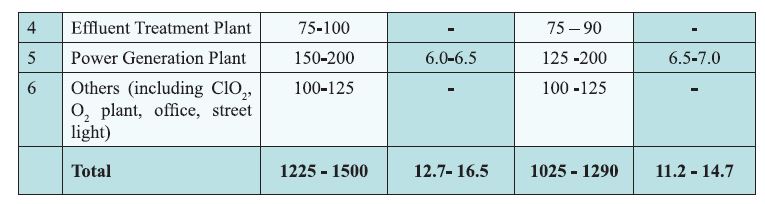
Table  Section-wise Energy Consumption in an Integrated Wood/Agro Based Mill Using Conventional Recovery System and the Integrated Agro Based Mill using Non-Conventional Recovery System. (Source: CPPRI)

Energy Consumption in Recycled Fiber (RCF)/Waste Paper Based Mills
The RCF based mills can be grouped into two categories depending on the manufacturing process and the final product. These are (1). Mills producing white varieties using De-inking and bleaching systems and (2). Mills without De-inking systems.
The overall energy consumption in the major unit operations of RCF based mill producing white  varieties using De-inking systems as well as the mill producing white and unbleached varieties without De-inking system is presented in Table
Table  Section-wise Energy Consumption of RCF Based Mill Producing White Grade of Paper Using Deinking and Oxidative Bleaching Systems as well as the Mill Producing White and Unbleached Varieties Without De-inking System. (Source: CPPRI)

Material and Energy Balance Calculations in Pulping and Paper Making Pulping
(i) Chemistry of Pulping
The two commonly used processes by Indian pulp & paper mills for pulping are soda and kraft processes. The soda process is used by medium sized agro based mills based on non-conventional recovery and the kraft process by large wood and agro based mills using conventional chemical recovery systems. In soda process sodium hydroxide is the major chemical used for cooking whereas in kraft process, cooking liquor or white liquor, an aqueous solution of sodium hydroxide (NaOH) and 
sodium sulphide (Na2S) is used for pulping. The hydroxyl ion (OH) and the hydrosulfide ion (SH ) are the active components in the cooking liquor. They originate from NaOH and Na2S as follows.
The concentration and total charge of the ions are the key elements in all kraft pulping reactions.

(ii) Terms Used in Pulping
Liquor to raw material ratio
Liquor to raw material ratio is a term that describes the amount of total liquor per unit weight of dry raw material in the digester. The moisture content of the raw material is also included in total liquor. The liquor to raw material ratio varies for each type of raw material and typically varies between three to five.

Alkali Charge
Two commonly used terms to indicate the chemicals charged in digester are total and active alkali.  Total alkali indicates concentration of sodium salts in white liquor on basis of equivalent amount of sodium oxide (Na,O) or as sodium hydroxide (NaOH) and it includes NaOH, Na2S, Na2CO3,1/2 Na2SO3 present in white liquor. The active alkali includes only NaOH and Na2S, which are the active chemicals for pulping. Both total and active alkali are expressed as percentage of dry lingo-cellulosic raw material weight are then referred to as total or active chemical / alkali charge.

Cooking Cycle
Various stages of cooking cycle are pre-steaming, raw material impregnation, cooking and blowing. Total cooking cycle is 3-4 hrs for a batch digester. The cooking however, takes place at a constant temperature of approximately 160 to 165° C for one to two hours. Most of the delignification takes place in the cooking stage.

Kappa Number
Kappa Number is a measure of residual lignin in the pulp. It is helpful to determine the degree of delignification achieved during cooking and to find out the bleach chemical demand during bleaching.

Example 16.1: Pulp cooking and steam requirements for digestion In a digester with 42.5 MT digester shell, 100 MT of chips with 50% moisture are cooked at 170°C by maintaining 1:4 bath ratio. The digester is filled with 112.5 MT of white liquor at 90°C and 37.5MT of black liquor at 85°C. Find out the total steam requirement per cook and steam per tonne of the chips and pulp.
- Sp. heat of chips at 50% moisture is 0.33, kcal/kg°C at 35°C
- Sp. heat of white liquor =0.91 kcal/kg °C at 90°C
- Sp. heat of Black liquor =0.94 kcal/kg° C at 85°C
- Sp. heat of digester shell =0.117 kcal/kg°C at 90°C.
- Temperature after blow = 105°C
- Radiation losses from digester = 8%
- Heat of reaction = -10% (exothermic)
- Sp heat of cooking liquor after cooking = 0.92 kcal/kg°C
- Pulp Yield= 40%
- Allowance for vent steam and heat blow = 5%
Solution:
The heat requirement for each component in digester is calculated as

Paper Machine
The paper making process is essentially a very large dewatering operation where a diluted solution of pulp suspension with less than 0.5 % fibre solids is formed into a web. Regardless of the nature of the pulp, whether it is chemical, mechanical or recycled from softwood, hardwood, agricultural residue, the basics of paper making are similar.

Complete process of water removal on the paper machine 1s carried out by four principal operations: 1) By “free drainage” on the fourdrinier, 2) By “suction” on the wire part, 3) By “pressing” on the press part and 4) by “evaporation” on the dryer part. The majority of the water is removed in the wire part to form the wet web of the paper. The sheet dryness after couch is 20-22%. The wet paper sheet after wire part is pressed and consolidated into a dense sheet with removal of moisture by pressing. After mechanical limits of water removal in the press is reached, the wet sheet enters the dryer part, where the dryness content of the sheet is increased by evaporation. The dryer section of a paper machine removes between 1.1 to 1.3 kg of water per kg of paper compared to 200 kg and 2.6 kg in the forming and press section respectively. It is significantly more expensive to remove water in the dryers than the forming and press section. The relative cost of dewatering are, forming section 10%, press Section 12% and dryer section 78 %. The dryer section is by far the largest consumer of thermal energy of the paper machine.

In this section some examples of the paper de-watering and steam requirements for paper drying are discussed.

Example 16.2:
A multicylinder fourdrinier paper machine is producing 100.0 tonnes cream woven paper with 6% moisture content without break per day. The consistency of the fibre suspension inside the head box is 0.5% and the dry content leaving the couch and the last press is 20% and 35% respectively. Determine
percentage of water removed,
By free drainage and suction on the wire part
By pressing on the press part
By evaporation from the dryers
Total quantity of water evaporated from the dryers per day
ao Tf
Neglect fibre losses, if any, with the back water.
Solution:
Basis: 100 tonnes /day production of cream woven paper
Hence, quantity of dry content carried by the paper per day = 0.94 x 100 = 94 tonnes

Ans:
a) Water removed on the wire — part = 97.98%
b) Water removed by the presses = 1.07%
c) Water evaporated by the dryers = 0.90%
d) Total quantity of water evaporated by the dryers perday = 168.57 tonnes

Example 16.3:
The average rpm of the dryer of a paper machine, producing 70 GSM Maplitho paper of 70% moisture, is 65. The deckle of the paper on the reel is 3.3 meters. The diameter of the drier is 1.5 meters. The steam pressure inside the drying cylinder is kept constant at 2.5 kg/cm’. If the sheet dryness after presses is reduced from 40% to 35%, Calculate:
a. Amount of additional water evaporated per day for paper at 93% dryness.
b. Amount of additional steam required per day.
Given that latent heat of evaporation of water at 100°C from the paper at zero pressure is 540 kcal/kg
and that of the steam in the drier at 2.5 kg/cm? at 126°C is 522 kcal/kg.

a) Evaporation when dryness after presses is 40 %
Moisture in finished paper will remain same
Therefore evaporation per kg of dry fibre = 1.857 — 0.075 = 1.782
Hence Evaporation per kg of paper produced = 1.782 x 0.93 = 1.657
Additional water evaporated = 1.657 — 1.325 = 0.332
Thus, additional water evaporated per day = 97.67 x 0.332
(kg of water evaporated / kg of paper produced) = 32.46 Tons

b. Since the steam pressure inside the drying cylinders is kept constant at 2.5 kg/cm2, therefore additional steam requirement shall be only due to the change in the dryness after presses.At 40% dryness, evaporation = 1.325 kg / kg of paper produced

Conclusions
The technological complexity and variation in process layouts in different pulp and paper mills based on wood, agro and RCF, leads to wide difference in energy consumption for production of similar products. A large number of energy management, best practices, advanced process control and State-of-Art technologies have been adopted by the mills, however still there is ample scope for improvement and energy efficiency enhancement in pulp and paper manufacturing. The energy auditors with sound understanding of pulp and paper mill processes can contribute significantly towards energy conservation, as the process optimization often leads to large savings.

-----------------
Chapter 17

ENERGY_PERFORMANCE_ASSESSMENT_FOR_EQUIPMENT_AND_UTILITY_SYSTEMS_(CHAPTER-15:ENERGY PERFORMANCE ASSESSMENT OF TEXTILE INDUSTRY)


ENERGY PERFORMANCE ASSESSMENT FOR EQUIPMENT AND UTILITY SYSTEMS

(CHAPTER-15:ENERGY PERFORMANCE ASSESSMENT OF TEXTILE INDUSTRY)

Introduction

The textile industry in India is one of the largest process industries in terms of its production and employment. Modern textile units are energy intensive requiring both thermal and electrical energy for their operation. The energy cost accounts for about 15 — 20% of the manufacturing cost. A typical energy consumption pattern of a composite textile mill is given in Figure 15.1. 

The textile industries with energy consumption equivalent to 3000 MTOE per year and above have been brought under designated consumer category as per Energy Conservation Act in India.


Textile Manufacturing Process

The four major stages of processing is follows as (Figure 15.2)

1.Spinning and weaving process (A)

2.Wet Process (B)

Spinning and weaving
a) Yarn Fabrication
Yarn fabrication is the process, which converts raw fiber into yarn or thread (figure 15.3). The fibers are prepared and then drawn out and twisted to form the yarn, which is then wound onto a bobbin or cone. The yarn fabrication is entirely dry, although some yarns may be dyed and finished as a final customer product
Opening / Blending: Raw materials (cotton and synthetic) are received in compact bales. The traveling type machine removes and separates the compressed fibers from each bale and open into the smallest flock gently. More bales can be processed at a time by this type and thus have long term
blending.
Cleaning: Cotton is passed through a series of machines (beaters) where opening and cleaning takes place simultaneously. Removes strange matters such as plant parts, seed hulls, dirt, etc, from the fibers. Speed of beater and clearance setting may be varied to achieve the desired level of cleaning. 
Carding: The fibers are formed into a mat by passing through two press rollers. This mat is continuously fed into the card. The sheet of carded fibers is removed through a funnel into a loose rope like strand called a sliver.
Combing: Processing cotton or wool stock through a series of needles/combs, to remove short fibers and strange matters and to form a sliver of maximum possible evenness.
Drawing: The drawing frame contains number of strands of card sliver and passes them through a set of rollers that rotate at successively faster speed. These rollers combine fibers into a single and more uniform strand. They draw out and lengthen fibers (5-6 times).

Roving: The drawn frame sliver is fed into the drafting arrangement, which attenuate the sliver. The yarn is stretched and slightly twisted to strengthen the strand (8 times the length and 1/8 the diameter).

Spinning: The rove fed into the drafting arrangement is further attenuated and twisted to the desired size to spin into the final yarn. The twist is generated by the spindle, which rotates at a higher speed. Each revolution of spindle imports one turn of twist to the strand. Finally the yarn (twisted fiber strand) is wound on bobbin mounted on spindle with the help of traveler. It uses four types of technologies: Ring spinning, rotor spinning, air jet spinning and friction spinning. Ring spinning is the most used in India due its wide adaptability for spinning different types of yarn. Rotor spinning is also widely used.

b) Fabric Production

Fabric production, the second step, involves weaving / knitting 

Weaving : Weaving is the most common method used for producing fabrics. The process is carried out of two sets of threads, which interlaces lengthwise yarns (warp yarns) with widthwise ones (weft or filling yarns).To prevent the warp yarns from braking during weaving,

the warp threads are coated with a size at 80 — 90 °C before weaving, to increase their tensile strength and smoothness. Natural starches are the most commonly used sizes, although compounds such as polyvinyl alcohol (PVA), resins, alkalisoluble cellulose derivatives, and gelatin glue have been used. The sizing compound is dried at 100-130 °C on the threads and remains a part of the cloth until it is removed in the subsequent processes.

Knitting :

In knitting fabric is formed through interlocking series of yarn loops by using hooked needles. Rows of stitches are formed so that each row hangs on the row behind it, usually using sophisticated, highspeed machinery.

Wet Processing

The fabric produced from the weaving or knitting is in rough condition, contains impurities and is often termed ‘grey’ fabric. Fabric processing (wet processing) is done to improve the appearance and serviceability of the fabric. The main operations carried out in this step include pre-treatment, dyeing, printing and finishing (figures 15.4)

Finishing
This stage includes the final operations necessary for making the textile presentable and attractive. It imparts the final aesthetic, chemical and mechanical properties to the fabric as per the end use requirements to improve appearance, texture or quality. The finishing operations include:

Drying: Drying removes the moisture from the fabric using drying machines such as stenter / drying cylinders.

Providing Dimensional Stability: This is one of the most important finishing operations. The fabric,
which is in a distorted condition, is brought to the required dimensions of width and length in a process called heat setting at around 140 - 150 °C. The heating medium used is thermic fluid/steam.

Calendering: A kind of glossy skin is formed on the fabric surface during calendering. The damp fabric is pressed hard against a hot, polished metal surface until it dries.

Softening: After calendering, the fabric becomes a little stiff. Breaking down this stiffness is called softening. The fabric is led through the softening machine so that it touches the studded rollers lightly and drags them around. In this way, the surface of the fabric is lightly disturbed making it much softer. Depending upon the type of fabric to be processed and the final product, any or all of the above processing operations can be carried out.

Monitoring of Energy Consumption in Textile Production Process
The objective of the assessment is to find out the specific energy consumption of both electrical and thermal per kg of yarn or fabric. The main processing areas in textile manufacturing that consume more energy are Spinning and Weaving, Wet Processing, and Garment Manufacturing. In addition, processes not directly related to production such as compressors, humidification systems etc. also consume significant energy.

Assessment of electrical energy consumption in the process
a) Spinning and weaving processes
Determine the processes in spinning and weaving where the largest amount of electricity is used and the data is to be tabulated as per table 15.1.
Table 15.1. Overview of electricity use in Spinning and weaving processing
b) Wet processing
Determine the processes in wet processing where the largest amount of electricity is used and the data
is to be tabulated as per table 15.2.
Table 15.2. Overview of electricity use in wet processing
Assessment of electrical energy consumption in utilities (other than process)
Electrical energy is used up in many areas other than process in the textile plant, including humidification, compressed air systems, lighting systems, electrical distribution network (as _ losses) and other utilities. Each major utility has to be assessed for energy consumption using online energy meters if available or with the portable power analyzer and tabulated as in table 15.3.
Table 15.3. Electrical energy use in other activities
Assessment of overall electrical energy use
After reviewing the main production areas as well as the other company activities, this step is intended to analyse the overall energy use and to calculate associated costs and ratios as shown in table 15.4. bBy comparing the current performance with the previous years or the industries average (benchmarking) it will be possible to identify energy saving opportunities. Since energy use may vary according to capacity utilization, the use of relative indicators, such as (kWh / kg of product) and (total energy costs / overall operating expense) is encouraged. This step will also help to continue with the further development of potential energy-saving changes.
Table 15.4. Overview of total electricity use in textile production

Assessment of overall thermal energy use
Besides electricity, thermal energy carriers such as steam and thermic fluid generated through coal, gas, oil, wood etc., are also used in other processes and activities. The thermal energy is predominantly used in wet processing activities. Since fuels have different calorific values thermal energy used is expressed in Metric Tonnes of Oil Equivalent (MTOE). The format for assessment of overall thermal
energy use is given in table 15.5.
Table 15.5. Total thermal energy use
Assessment of overall energy use
The overall energy use can be calculated from the electricity bills and fuel bills for one year period
and expressed in MTOE as shown in table 15.6.
Table 15.6. Total overall energy in textile production
Benchmarking / Energy Performance Index
The generated data can be further used for benchmarking as shown in table 15.7. In an internal
benchmarking, the current performance can be compared with past values in order to observe the
improvements. External benchmarking will require comparison with industry average or competitors.
The benchmarking parameters commonly used are kWh/kg and kcal/kg of yarn or fabric.
Table 15.7. Benchmarking / Performance Index

Performance Monitoring of Process Equipment
The major energy consuming equipment in textile processes are ring frames, carding, winding and blow room machinery. Since the ring frame is single largest consumer, the performance monitoring is limited to ring frame. Similar approach can be adopted for other equipment. In the wet process the energy intensive equipment are stenters and dyeing machines, performance evaluations of which are given in this chapter.

Performance Evaluation of Ring Frame
The energy consumption depends on yarn count, mix ratio of cotton and polyester, spindle speed, ring diameter, weight of traveler, package diameter, lift, spindle gauge, spindle wharve diameter, type of spindle tape used, front roller speed, maintenance practices of ring frames, type of pneumafil system, motor drive system, etc. The spinning energy performance is reported in terms of kWh consumption per kg of yarn produced at an average reference count. Also there is a convention of reporting specific energy consumption as kWh consumption per spindle shift. Both the figures are bench marked against best practice values and energy saving opportunities implemented accordingly.

Motor Performance Monitoring:
Since the spinning section comprises of large number of motors, load analysis of motors has to be carried out and potential for shuffling, operating in star mode, retrofitting of soft starters energy saver, replacement of motors etc need to be analysed. The procedures described in Chapter-5 may be adopted.

Performance Evaluation of Stenter —Hot Air Dryer
The stenter is a hot air dryer, with the fabric passing through on a chain drive, held in place by either clips or pins. The stenter has many chambers and in each chamber, the air is blown through the radiators in which steam or thermic fluid is passed. The heated air is circulated above and below the fabric and is exhausted to the atmosphere by exhaust fans. Direct firing of natural gas is also practiced in stenters. Apart from drying, the stenter is a versatile piece of equipment used for pulling the fabric to width, chemical finishing, heat setting and curing. Refer figure 15.6 (a & b) for the schematic diagram.

Performance Evaluation Methodology
Efficiency estimation of Stenters/dryers can be done by measurement of moisture content in material before and after the dryer to estimate total moisture removal from the substance. The energy required to drive out this moisture is termed as useful energy spent in the dryer. By measuring the total input heat energy to the dryer, the dryer efficiency is estimated.

Parameters to be measured
Measure moisture content of material at inlet to dryer
Measure moisture content of material at outlet of dryer
Measure mass flow rate of dried material.
Measure input thermal energy to dryer which could be in the form of (i) hot air input (ii)
Steam heating or (111) electrical heating through various direct measurements or indirectly
from quantity of fuel fired and combustion efficiency assessments for direct fuel fired dryers.
Example 15.1
The throughput of a textile stenter is 1000 kg/hr. The inlet moisture content of the cloth is 50% and the outlet moisture is 5%. The inlet and outlet temperature of the cloth is 28 °C and 80 °C. The stenter is supplied with steam at an enthalpy of 660 kcal/kg, the condensate leaves at 90 °C. The flow rate of steam is 1000 kg/hr. Estimate the overall thermal efficiency of the dryer. The latent heat of evaporation of water is 540 kcal/kg.


Performance Evaluation of Dyeing Machines
The different types of machines used in the aqueous dyeing of textile fabrics are open width Jigger dyeing (figure 15.7), Jet dyeing, rope form Winch dyeing etc. These are operated at atmospheric pressure or higher pressure and temperatures below or above 100°C depending on the substrate being dyed. The major energy usage in dyeing is thermal energy in the form of steam. The bath (liquor) ratio may vary from 1:4, 1:6 to 1:10 or higher (1.e.1 kg of textile material to 4, 6 to 10 litres of water on weight ratio) based on the dyeing types (batch / continuous). The dye colour and chemicals are mixed in the water heated by steam.
  Effect of material — to — Liquor ratio on consumption of steam
 Energy requirement for dyeing cotton fabrics
Energy Balance Calculation for dyeing machines
The approach to calculate energy balance is more or less similar to all dyeing machines. Dyeing requires steam to heat the liquor to the requisite temperature and maintain the temperature for a specific period of time.

Energy input is calculated in the following ways:
a) Steam flow rate can be calculated by collecting the quantity of steam condensate for a specified time period.
b) Enthalpy of steam can be drawn from the pressure of steam using steam table/Mollier chart.
Heat Load (at input) = Ms x total enthalpy of steam
Energy output is calculated in the following ways:
a) The heat absorbed by the fabric and vessel.
b) The heat taken by the liquor.
c) The heat through radiation and convection by machine surface
d) Heat in the vapours
*Since the values are insignificant and tedious to calculate, it will be reasonable to assume that fabric and other losses account for additional 10% of the steam input.

Specific consumption of steam in dyeing is calculated as kg of steam per kg of cloth.

Example 15.2. 100 kg of fabric is to be dyed in a jigger. The dye liquor is heated from 30 to 80 °C.
Calculate the quantity of steam required at 2 kg/cm2 (g) and specific steam consumption if the liquor
ratio is 1:6.
Using heat balance equation,
Heat energy input = Heat energy output


Performance Monitoring of Utilities
The major energy utilities of textile industry are:
i. Boilers and steam systems
ii. Thermic fluid heaters
ii. Compressed air systems
iv. Humidification systems
Boiler and Steam Systems
The steam boiler, as a supplier of thermal energy for heating purposes, is the heart of a dye house in wet processing operations. Different fuels are used to operate the steam boilers viz., wood, coal, oil and gaseous fuels based on the cost and availability, calorific value, ease of combustion and flue gas
characteristic.
Refer to chapter-1 of this book for Performance evaluation of boiler (Direct & Indirect method of
efficiency testing) and chapter-3 of book - 2 Steam systems.

Thermic Fluid Heaters
The thermic fluid heaters provide thermal energy for high temperature operations such as drying of fabric in stenter after dyeing operation in wet processing. The drying and finishing of textiles are highly energy intensive processes since it involves the use of very hot air (140-200°C) to either remove chemically held water from the textiles by evaporation or physically /chemically set the textile  materials.

Employing petroleum - based fluids as the heat transfer medium, these heaters provide constantly maintainable temperatures for the user equipment.
The modern oil fired thermic fluid heater (refer figure 15.8) consists of a double coil, three pass construction and fitted with modulated pressure jet system. The thermic fluid, which acts as a heat carrier, is heated up in the heater and circulated through the user equipment. There it transfers heat for the process through a heat exchanger and the fluid is then returned to the heater. The flow of thermic fluid at the user end is controlled by a pneumatically operated control valve, based on the operating temperature. The heater operates on low or high fire depending on the return oil temperature, which varies with the system load.
The advantages of these heaters are:
¢ Closed cycle operation with minimum losses as compared to steam boilers.
¢ Non-Pressurized system operation even for temperatures around 250 °C as against 40 kg/cm2
steam pressure requirement in a similar steam system.
¢ Automatic control settings, which offer operational flexibility.
¢ Good thermal efficiencies as losses due to blow down, condensate drain and flash steam do not
exist in a thermic fluid heater system.

Performance Evaluation
Thermic fluid heater efficiency can be tested by the following methods:
1. The Direct Method: Where the energy gain of the working thermic fluid is compared with the energy content of the heater fuel.
2. The Indirect Method: Where the efficiency is the difference between the losses and the energy input. It is also called as heat loss method.

The Direct Method of Testing: This is also known as ‘input-output method’ due to the fact that it needs only the useful output in thermic fluid and the heat input (i.e. fuel) for evaluating the efficiency. This efficiency can be evaluated using the formula


Example 15.3. Test Data and Calculation
Heat output data:
Flow rate of thermic fluid : 68 m3/h
Inlet temperature of thermic fluid =: 200 °C
Outlet temperature of thermic fluid : 212°C
Specific heat of thermic fluid : 2.223 kJ/kg°C
Density of the thermic fluid : 826 kg/m3
Heat input data:
Quantity of fuel oil consumed (Input) : 46 kg/h
GCV of fuel oil : 10000 kcal/kg
Calculation:
Heat output (thermic fluid) = 68 x 826 x (2.223/4.187) x (212-200) = 357902.5 kcal/h
Heat input (fuel) = 46 x 10000 = 460000 kcal/h
Thermic fluid heater efficiency = (357902.5 / 460000) x 100 = 77.8%
(Note: The indirect method for efficiency testing of thermic fluid heater is similar to that for boiler
testing; refer to chapter -1 Boiler, for Indirect Method)

Compressed Air Systems
The intensity of compressed air use is high in spinning section due to automated machines in spinning section. Mostly reciprocating/screw compressors are used. For the performance evaluation of  compressed air systems, refer to chapter-8 of this book and chapter-3 of book-3.

Humidification Systems
Need for Humidification: The relative humidity and temperature level needs to be maintained within a prescribed tolerance limits at all steps of textile processing so as to avoid the problems of yarn breakage in dry and brittle condition and also to minimize the build up of static charge so as to reduce dust and fibre fly (fluff). For this purpose, spray air washers using spray water as the medium for adiabatic cooling of air (by direct evaporation of water into the air stream thereby reducing the air’s dry bulb temperature and raising its humidity) are extensively used in humidification systems. The system (figure 15.9) consist of a chamber containing multiple banks of spray headers with spray nozzles, a tank for collecting spray water as it falls and an ‘eliminator section’ with PVC blades having 3 or 4 bends for removing droplets of water from the air which is humidified after passing through the curtain of spray water, before discharge to the air ducts for distribution to the humidified areas.

Psychrometrics of humidification:
The room sensible heat load calculations are worked out as the sum-total of:
¢ Heat dissipation from the machines operating kW load in various departments.
¢ Lighting load
¢ Solar heat gain through insulated roof
¢ Occupancy load
¢ Heat gain from supply air fan motors
Note: For detailed heat load estimation, ASHRAE - HVAC handbook can be referred.

Saturation efficiency
Higher saturation efficiency of air washer is defined as the ratio
Improving the saturation efficiency reduces the temperature of air leaving the air washer thereby increasing the delta ‘T’ (temperature rise of saturated air due to heat pick up in the department) for a specific heat load and relative humidity condition in the department with consequent reduction in required supply air quantity and fan motor power consumption.

Example 15.4.
Temperature of humidified air leaving the air washer based on summer outside design dry bulb (40°C)
and wet bulb temperatures (25°C) and design saturation efficiency (95%) is calculated as follows and
plotted on the psychrometric chart (figure 15.10).
Leaving Air Temperature from Air - Washer
= Entering Air DBT - (Ent. Air DBT - Ent. Air WBT) x % Saturation efficiency
Air temperature leaving the air washer = 40-(40-25) x 0.95 = 40-14.25 = 25.75°C.

With change in ambient air wet bulb temperature, the air-temperature leaving the air washer will also vary along with a change in the department’s inside dry bulb temperature, even though the inside design relative humidity condition remains constant.
The line of supply air temperature rise in the department due to heat gains is plotted horizontally, starting from the point of “leaving air temperature condition” after humidification in air washer, till it reaches the design relative humidity line for the corresponding department.
The required supply air quantity is calculated as follows:

Example 15.5. In a typical spinning mill humidification application, the sensible heat load of the spinning department is estimated as 10,03,000 kcal/h, temperature rise was 8°C and the density and specific gravity of the air were 1.2 kg /Nm3 and 0.24 kcal/kg °C, respectively. Calculate the supply air
quantity for the department.

Humidification design parameters for a typical spinning mill with summer outside design conditions of 40 °C DBT & 25 °C WBT
Performance Evaluation of Fans
The energy consumption in humidification systems is dominated by fans accounting for 90%. Hence any attempt to reduce energy consumption in humidification system depends on efficient operation of fans, optimizing number of air changes, reducing pressure drops in ducting and use of energy efficient fans and motors. For performance evaluation of fans, blowers and duct systems, refer to chapter-6 of this book.

Solved Example:
1) 125 kg of fabric is to be dyed in a jigger. The dye liquor is heated from 30 °C to 90 °C. Calculate steam (steam enthalpy 660 kcal/kg) requirement per batch and specific steam consumption
(kg of steam per kg of cloth), if liquor ratio is 1:6.5; allowing 10% margin for losses.
2) In a textile mill, a thermic fluid heater of 15 lakh kcal/hr capacity is meeting process heat requirements.
The observed parameters of thermic fluid heater are:
Thermic fluid circulation rate - 100 m3./hr
Outlet temperature of fluid - 270 °C
Return temperature of fluid - 256 °C
Specific heat of fluid - 0.55 kcal/kg °C
Density of fluid - 830 kg/m3
Present coal consumption - 300 kg /hr
GCV of coal - 3500 keal/hr
i) What is the % loading of the thermic fluid heater?
11) What is the existing thermal efficiency?
ii1) The management is proposing to add a five chamber, (each chamber | Lakh kcal/hr duty) to the heater. Will it be able to take the load?

------------------------
Chapter 16

Followers