ENERGY_PERFORMANCE_ASSESSMENT_FOR_EQUIPMENT AND UTILITY SYSTEMS
(CHAPTER-9:ENERGY PERFORMANCE ASSESSMENT OF HVAC SYSTEMS)
Introduction
Air conditioning and refrigeration consume significant amount of energy in buildings and in process industries. The energy consumed in air conditioning and refrigeration systems is sensitive to load changes, easonal variations, operation and maintenance, ambient conditions etc. Hence the performance evaluation will have to take into account to the extent possible all these factors.
Purpose of the Performance Test
The purpose of performance assessment is to verify the performance of a refrigeration system by using field measurements. The test will measure net cooling capacity (tons of refrigeration) and energy requirements, at the actual operating conditions. The objective of the test is to estimate the energy consumption at actual load vis-a-vis design conditions.
Performance Terms and Definitions
Tons of refrigeration (TR): One ton of refrigeration is the amount of cooling obtained by one ton of
ice melting in one day: 3024 kcal/h, 12,000 Btu/h or 3.516 thermal kW.
Net Refrigerating Capacity: A quantity defined as the mass flow rate of the evaporator water multiplied by the difference in enthalpy of water entering and leaving the cooler, expressed in kcal/h, tons of Refrigeration. It means the actual operating TR.
kW/ton rating: Commonly referred to as efficiency, but actually power input to compressor motor divided by tons of cooling produced, or kilowatts per ton (kW/ton). Lower kW/ton indicates higher efficiency.
Coefficient of Performance (COP): Chiller efficiency measured in W output (heating) divided by W input (electric power). COP refers to heating efficiency of an air conditioner (heat pump). For example if an air conditioner generates 5 kW of heat from one kW electrical input, its COP is said to be 5.0.
Energy Efficiency Ratio (EER): Performance of smaller chillers and rooftop units is frequently measured in EER rather than kW/ton. EER is calculated by dividing a chiller’s cooling capacity (in watts) by its power input (in watts) at full-load conditions. This definition of EER has been adopted in BEE star labeling programme. For example if an air conditioner generates 4000 W (1.14 TR) of cooling from 1000 W electrical input, its EER is said to be 4.0. The higher the EER, the more efficient the unit.
EER is also defined as ratio of chiller’s cooling capacity (in BTU/hr) to its power input (in watts) at full-load conditions. For example if an air conditioner generates 13648 BTU/hr (1.14 TR) of cooling from 1000 W electrical input, its EER is said to be 13.65.
Components of HVAC Systems
The various components of HVAC systems are
1) Chiller plant
a) Evaporator unit
b) Compressor unit (in vapour compression refrigeration system)
c)Absorber and Generator unit (in vapour absorption refrigeration system)
d) Condenser unit (air cooled / water cooled and condenser fans / cooling tower fans)
e) Air handling unit (with fans / blowers)
f) Primary and secondary chilled/cooling water pumps
Procedure for Performance Evaluation of Vapour Compression Refrigeration (VCR) System
After establishing the steady-state conditions, three sets of data shall be taken, preferably at a minimum of five-minute interval. To minimize the effects of transient conditions, test readings should be taken simultaneously to the extent possible in all components of HVAC system.
To determine the net refrigeration capacity at the evaporator
The test shall include a measurement of the net heat removed from the water as it passes through the evaporator by measurement of the following:
a. Chilled water flow rate through the evaporator coil
b. Chilled water inlet / entering and outlet / leaving temperatures
The heat removed from the chilled water is equal to the product of the chilled water flow rate, the water temperature difference, and the specific heat of the water. The net refrigeration capacity in tons shall be obtained by the following equation:
The accurate temperature measurement is very vital in refrigeration and air conditioning and least
count should be at least one decimal.
Methods of measuring the water flow
In the absence of an on-line flow meter the chilled water flow can be measured by the following
methods
1.In case where hot well and cold well are available, the flow can be measured from the tank level dip or rise by switching off the secondary pump.
2.Non invasive method would require a well calibrated ultrasonic flow meter using which the flow can be measured without disturbing the system
3. If the waterside pressure drops are close to the design values, it can be assumed that the water flow of pump is same as the design rated flow.
Measurement of compressor power
The compressor power can be measured by a portable power analyser which would give reading directly in kW.
If not, the ampere has to be measured by the available on-line ammeter or by using a tong tester. The power can then be calculated by multiplying ampere with voltage and power factor.
To determine the heat rejected at the condenser
Heat rejected at condenser = Cooling load + Work done by compressor
The shaft power kW absorbed (work done) by the compressor can be derived by measuring the motor
input power multiplied by motor operating efficiency.
Heat rejected at the condenser can be measured as under:
Water cooled condenser :
a. Measure the water quantity flowing through the condenser using flow meter.
b. Measure the inlet and outlet temperature of water in the condenser using digital thermometer.
Air cooled condenser :
a. Measure the air quantity flowing across condenser coil.
b. Measure the inlet and outlet temperatures of air using digital thermometer.
Since this process is normally a sensible heating, the capacity can be established by calculating only sensible heat gain.
Measurement of air flow
Air flow may be measured with any of the following instruments:
a) Vane Anemometer
b) Hot wire anemometer
The measuring instruments should be duly calibrated. The least count for anemometers should be 0.1 m/s. Air flow rate is calculated as the multiplication product of the average air velocity in the plane of measurement and the flow area.
Performance calculations
The energy efficiency of a chiller is commonly expressed in one of the three following ratios:
First calculate the kW/ton rating from the measured parameters.
From this parameter, the other energy efficiency parameters can be calculated. It may be observed that
the COP and EER values will be numerically the same. EER is used as a performance indicator only for window, split and package air conditioners.
Performance evaluation of air conditioning systems
For centralized air conditioning systems the air flow at the air handling unit (AHU) can be measured with an anemometer. The dry bulb and wet bulb temperatures can be measured at the AHU inlet and outlet. The data can be used along with a psychrometric chart (Figure 9.1) to determine the enthalpy (heat content of air at the AHU inlet and outlet)
Heat load can also be calculated theoretically by estimating the various heat loads, both sensible and latent, in the air-conditioned room (refer standard air conditioning handbooks). The difference between these two indicates the losses by way of leakages, unwanted loads, heat ingress etc.
Evaluation of fans / blowers
The following readings can be taken for evaluation.
a) Air flow rate
b) Static pressure developed by the fan pitot tube and manometer can be used for measuring the differential head.
c) RPM of the fan using tachometer / stroboscope.
d) Current (amps), Voltage, power factor and power consumed (kW) by the fan motor using power analyser.
The above readings establish the fan performance and can be compared with the design parameter.
Evaluation of primary and secondary water pumps
The following readings can be taken for evaluation.
a) Water flow rate
b) Head pressure developed. (measured with the help of suction and discharge pressure gauge)
c) RPM
d) Current (amps), Voltage, Power drawn (kW) by the motor.
The above readings can be compared with the performance chart or design parameter.
Performance assessment of Vapour Compression Refrigeration (VCR) system:
Examples
Example 1: The following are the data collected during the energy audit of chilled water system in a chemical plant. Find out the kW/TR and COP?
Measurements data:
Example 2: Estimation of Performance for an office air conditioning system working on Vapour
Compression Chilling Package having direct expansion type air handling unit.
Inference: The performance parameters estimated above are actual values at operating conditions, which should be compared with the design values. If there is any deviation from the design specifications, analysis of the above energy equipment have to be carried out.
Example 3: An air handling unit was evaluated for its performance in a study and the following parameters were recorded. The air velocity was measured at different locations of the face area of 1.19
m2 for AHU unit and its average velocity was calculated as 1.3 m/s. The dry and wet bulb temperatures of the air at the inlet of the unit are 29.4 and 24.4 °C, and at the outlet 24.4 and 19.2°C, respectively. Using psychrometric chart, determine the enthalpy of the air at inlet and outlet conditions and calculate the heat load in TR.
Air flow rate = (1.19 m2x 1.3 m/s) x 3600 = 5569.2 m3/h
Assuming air density as 1.2 kg/ m3
Mass flow rate of air = 5569.2 x 1.2 = 6683 kg/h
From psychrometric chart, (for corresponding dry and wet bulb temperatures of air)
Enthalpy of the inlet air = 73.34 kJ/kg
Enthalpy of the outlet air = 54.5 kJ/kg
Heat load (TR) = [6683 x (73.34 — 54.5)] / (4.18 x 3024)
= 10TR.
Procedure for Performance Evaluation of Vapour Absorption Refrigeration (VAR) System
It should be ensured that the evaporator, condenser and generator are nearly at same operating conditions throughout the duration of the test. The vapour absorption system auxiliaries include chiller water pumps, condenser water pumps, cooling tower fans and performance assessment of these auxiliaries can be carried out in the same manner as applicable to vapour compression refrigeration system auxiliaries.
Estimation of performance at evaporator side
The performance evaluation involves the measurement of following parameters.
Refrigeration effect (Qe )
¢ Chilled water flow rate in the evaporator.
¢ Chilled water temperatures at the evaporator inlet and outlet.
Thermal power input (Qin )
¢ Steam mass flow rate in case of steam heated vapour absorption chilling package.
¢ Fuel flow rate in case of direct fuel fired vapour absorption package.
Measuring instruments:
The measuring instruments should be duly calibrated.
1.Direct reading thermometers can be used for measuring temperature. The least count for temperature indicating instruments should be 0.1°C.
2. The method mentioned in VCR system can be used for water flow rate measurement.
3. For steam heated vapour absorption chilling package, the thermal power consumption may be measured with any of the following instruments:
a. Calibrated in-line steam flow meter.
b. Collection of condensate in calibrated volume (container) for a defined time period. The
time period should be measured with a digital chronometer (stop-watch) with least count of 1/100 second. The condensate may be cooled to reduce the flash steam losses.
4. For fuel fired vapour absorption systems, the thermal power may be measured with any of the following instruments:
a. Calibrated In-line fuel flow meter.
b. Fuel level difference (for liquid fuels) for a defined time period in a calibrated day tank. The time period should be measured with a digital chronometer (stop-watch) with least count of 1/100 second.
Performance calculations:
Coefficient of performance, COP at evaporator side


Estimation of performance at condenser side (water cooled condenser)
The performance evaluation involves the measurement of following parameters.
Heat rejected at the condenser (Qc )
1. Cooling water flow rate in the condenser.
2. Cooling water temperatures at absorber inlet and the condenser outlet.
Thermal energy input (Qin )
¢ Steam mass flow rate in case of steam heated vapour absorption chilling package.
¢ Fuel flow rate in case of direct fuel fired vapour absorption package.
Determination of refrigeration effect and COP:
i. The refrigeration effect and COP can be determined from the overall heat balance of the condenser and VAR system.
ii. Heat rejected at the condenser (Qc) is equal to refrigeration effect heat (Qe) plus thermal energy input (absorbed) by the system (Qin).
Performance calculations:
a) COP at condenser side for steam heated vapour absorption package
b) COP at condenser side for direct fuel fired vapour absorption packages
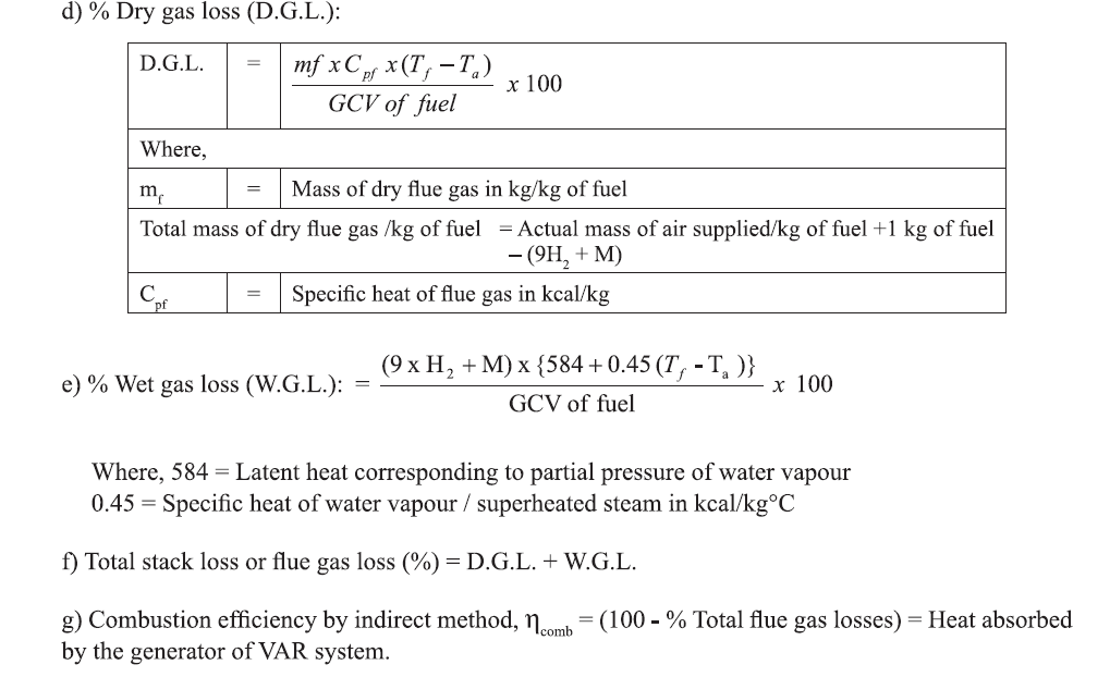
Combustion Efficiency Calculations:
The method described below can be used for estimating combustion efficiency of a direct fuel fired absorption chilling unit. The methodology is the “Indirect Method” to estimate combustion efficiency

Wherein the losses are estimated from flue gas analysis to estimate efficiency.
Observations:
Calculations:
Note: In this method only the major combustion losses namely, dry and wet flue gas losses are
considered. All other losses are considered insignificant and hence ignored.
Performance assessment of Vapour Absorption Refrigeration (VAR) system: Example
This is a sample calculation for a Vapour Absorption Chilling Package. Measurements are shown along
with equations and estimation of results.
Equipment Specification for VAR system
Method 1: Evaporator side
Estimation of performance from refrigeration effect in evaporator for steam heated vapour chilling
packages (Chilling water)


Method 2: Condenser side
Estimation of performance from heat rejection in Water Cooled Condenser for steam heated vapour
absorption chilling packages (Cooling water)

Inference: The performance parameters estimated above show a deviation from the actual design
values. This may due to operation of the chiller at less than 50% load.
Solved Example:
In an air conditioning system of a food processing industry, the cold air flow rate is 20,000 m3/hr at a
density of 1.2 kg/m3 .The inlet and outlet enthalpy of the air are 105 kJ/kg and 80 kJ/kg. The COP of
the existing vapour compression system is 3.75. The efficiency of the motor coupled with the compressor is 90%.
The management wants to install a Vapour Absorption System (VAR).The saturated steam for VAR
will be supplied either from a new waste heat boiler to be installed with the existing DG sets or from
the existing FO fuel fired boiler. The plant is operating for 8000 hr/annum. The investment of VAR
system is Rs. 20 lakhs. The investment for waste heat boiler is Rs. 6 lakhs. The power cost is Rs. 6/
kWh.
As an energy auditor which one of the following options will you recommend to the management?
Option-1: Supply steam from the existing FO fuel fired boiler to VAR system and avoid the investment of waste heat boiler
Option-2: Supply steam from the waste heat boiler, which needs an investment in addition to VAR
system
The steam consumption per TR will be 5.5 kg/TR. The cost of FO is Rs.32,000/ tonne. The evaporation ratio of the existing FO fired boiler is 14. Neglect losses in transmission of steam and chilled water.
Solution:


 Wherein the losses are estimated from flue gas analysis to estimate efficiency.


Comments