ENERGY PERFORMANCE ASSESSMENT OF BUILDINGS
AND COMMERCIAL ESTABLISHMENTS
Introduction
The major energy consuming utilities of the buildings and commercial establishments are HVAC, lighting, office systems and other loads. In order to achieve reduction in the energy costs by proper utilization, operation and maintenance of the existing building equipment and utility systems, performance evaluation is required. In addition there is also a need to review the building envelope for minimizing the heat gain and maximizing daylighting usage in the building.
Purpose of the Performance assessment
The purpose of the performance assessment is to analyse the building for its envelope, load profile , equipment and system efficiencies and the energy optimization scope for a building by quantifying energy usage. It helps to evaluate the present status, set up a baseline and compare with the standard norms and benchmark.
Determining Energy Performance Index (EPI) and Average Annual Hourly EPI (AAHEPDI)
The different sources of energy used in the building have to be identified with the help of facility people and walkthrough survey of the facilities.
Step 1 -Data Collection
The total electrical energy consumption of the facility both Grid and Captive is to be collected month wise over a one year period.
The total built up area of the building needs to be collected. The built up area is the carpet area plus area covered by thickness of walls plus balconies etc., and would exclude parking areas.
The operating hours per day and working days per year have to be collected.
Step 2 -Analysis
Energy performance Index (EPI): Energy Performance Index is a measuring tool to evaluate the performance of the building in terms of the total energy consumption and the total built up area.
Average Annual Hourly Energy Performance Index (AAHEPI): The number of operating hours
of a building may vary depending on the nature of operation. The AAHEPI enables the performance
assessment taking into account the actual operating hours which will be more meaningful. AAHEPI
is defined as follows
Example 14.1: Estimation of EPI and AAHEPI
A commercial building located in warm and humid climatic region, has a built up area of 17814 m’.
The annual energy consumption of the building is 3735640 kWh from the Grid and 2964758 kWh
from captive DG sets. The facility operates 12 hrs a day and 250 days ina year. Calculate the EPI and
AAHEPI.
Solution:
Significance of Building Envelope
The building envelope is the interface between the interior of the building and outdoor environment including the walls, roof and foundation. By acting as a thermal barrier, the building envelope plays an important role in regulating interior temperatures and helps in determining the amount of energy required to maintain thermal comfort. The envelope design and orientation also determines the amount of artificial lighting required in the building.
Envelope design basics
The energy performance of a building envelope is influenced by number of factors. For example, these may include design elements such as the physical orientation of the building and the amount of sunlight that penetrates into the interior work spaces. Other factors may also include heat transfer characteristics (both losses and gains) and location of the building envelope components such as walls, windows, doors, floors and roofs. The energy performance of the building may also be influenced by any natural air infiltration through the building envelope (e.g. cracks). The sources of heat gain into the building space are depicted in figure 14.1.
An integrated building design considers the envelope, the heating, ventilation, cooling (HVAC) system
and the lighting system as a whole, rather than dealing with these independently. Changing the specifications of one system can affect the performance of the other two significantly. For instance, investments in good insulation of the roof, energy-efficient windows or increased envelope air tightness can result in a smaller HVAC system, thereby reducing its first cost as well as recurring energy cost.
Similarly, an inefficient lighting system not only increases lighting energy consumption but could also increases the cooling load on HVAC system, thereby increasing the energy consumption further. When a building is in cooling mode, solar heat gains need to be minimized within the building space while optimizing daylight and intake of outside air. Outside air could be introduced particularly during evening/night hours when the ambient temperature drops. This strategy cools the thermal mass in the building during night hours and reduces overall cooling load during the next day. On the other hand, if the building is in a heating mode, the envelope needs to be designed with appropriate glazing selection
coupled with shading strategy to enhance solar heat gains during daytime. Therefore in practice, the architects and building designers need to integrate and balance these varying requirements considerations while designing an energy-efficient building.
Assessment of HVAC Systems
The detailed layout of HVAC plant should be collected along with the design parameters of all the HVAC equipment. The main objective of the assessment will be to determine the actual operating refrigeration load (TR), measure the actual power drawn and compare the actual kW/TR with the design.
The operating parameters of Chiller plant has to be monitored for one day. The temperature measurements with 0.1 least count have to be carried out periodically for chilled water and cooling water. The flow measurements are to be carried out with an ultrasonic flow meter. Simultaneous power measurements
need to be done with the compressor motor, chilled water, cooling water pumps and cooling tower fans/condenser fans. The detailed calculation will have to be performed for various equipment/systems
as given in the table 14.1 below.
Table 14.1 Performance Calculations Reference
If further in-depth assessments need to be performed for calculating the prevailing air conditioning
load, the following method may be pursued. This method merely highlights the concepts and intensity
behind the cooling load calculations. The detailed calculations are outside the scope of this book
as they are heavily dependant on vast data from ASHRAE hand book.
Terminology used in estimating cooling load
Commonly used terms relative to heat transmission and load calculations are defined below in
accordance with ASHRAE Standard 12-75, Refrigeration Terms and Definitions.
Space — is either a volume or a site without a partition or a partitioned room or group of rooms.
Room — is an enclosed or partitioned space that is usually treated as single load.
Zone — is a space or group of spaces within a building with heating and/or cooling requirements
sufficiently similar so that comfort conditions can be maintained throughout by a single controlling device.
Cooling Load Temperature Difference (CLTD) — an equivalent temperature difference used for calculating the instantaneous external cooling load across a wall or roof.
Sensible Heat Gain — is the energy added to the space by conduction, convection and/or radiation.
Latent Heat Gain — is the energy added to the space when moisture is added to the space by means of vapor emitted by the occupants, generated by a process or through air infiltration from outside or adjacent areas.
Radiant Heat Gain — the rate at which heat absorbed is by the surfaces enclosing the space and the objects within the space.
Space Heat Gain — is the rate at which heat enters into and/or is generated within the conditioned space during a given time interval.
Space Cooling Load — is the rate at which energy must be removed from a space to maintain a constant space air temperature.
Thermal Transmittance or Heat Transfer Coefficient (U-factor) — is the rate of heat flow through a unit area of building envelope material or assembly, including its boundary films, per unit of temperature difference between the inside and outside air. The U-factor is expressed in W/ m2°K)
Thermal Resistance (R) — is the reciprocal of a heat transfer coefficient and is expressed in m2°K/W. The value of R is also used to represent Thermal resistivity, the reciprocal of the thermal conductivity.
Types of loads
There are two distinct components of the air conditioning load;
1. The sensible load (heat gain)
2. The latent load (water vapor gain).
Sensible Loads: Sensible heat gain is the direct addition of heat to a space, which shall result in increase in space temperatures. The factors influencing sensible cooling load:
1. Solar heat gain through building envelope (exterior walls, glazing, skylights, roof, floors, over crawl space)
2. Partitions (that separate spaces of different temperatures)
3. Ventilation air and air infiltration through cracks in the building, doors, and windows
4. People in the building
5. Equipment and appliances operated in the summer
6. Lights
Latent Loads: Latent heat gain is the heat contained in water vapor. Latent heat does not cause a temperature rise, but it constitutes a load on the cooling equipment Latent load is the heat that must be removed to condense the moisture out of the air.
The sources of latent heat gain are:
1. People (breathing)
2. Cooking equipment
3. Housekeeping, floor washing etc.
4. Appliances or machinery that evaporates water
5. Ventilation air and air infiltration through cracks in the building, doors, and windows
The total cooling load is the summation of sensible and latent loads.
Cooling Loads Classified by Inside-Outside Environment
Buildings can be classified as envelope-load-dominated and interior-load-dominated. The envelope heat flows are termed as “external loads”, in that they originate with the external environment. The other loads are termed as “Internal loads”, in that they are generated from within the building itself. The percentage of external versus internal load varies with building type, site climate, and building design decisions. It is useful to identify whether internal or external loads will dominate a building, as this information should substantially change the focus of design efforts related to control and energy efficiency.
External Loads
External cooling loads consist of the following:
1. Sensible loads through opaque envelope assemblies (roofs, walls, floors)
2. Sensible loads through transparent or translucent envelope assemblies (skylights, windows,
glazed openings)
3. Sensible loads through ventilation and infiltration (air leakage)
4. Latent loads through ventilation and infiltration.
Internal Loads
1. Typical sources of internal heat gain are people, lights, cooking processes, and other heatgenerating equipment, such as motors, appliances, and office equipment.
2. While all of these sources contribute sensible heat to the space, people, cooking processes, and some appliances (such as a coffee maker) also contribute latent heat to the space.
CLTD/SCL/CLF Method of Load Calculation (ASHRAE Handbook Fundamentals 1997)
The heat gain in to the building is not converted to cooling load instantaneously.
CLTD (cooling load temperature difference),
SCL (solar cooling load factor), and
CLF (cooling load factor): all include the effect of
(1) time-lag in conductive heat gain through opaque exterior surfaces and
(2) time delay by thermal storage in converting radiant heat gain to cooling load.
This approach allows cooling load to be calculated manually by use of simple multiplication
factors.
a. CLTD isa theoretical temperature difference that accounts for the combined effects of inside and outside air temp difference, daily temp range, solar radiation and heat storage in the construction assembly/building mass. It is affected by orientation, tilt, month, day, hour, latitude, etc. CLTD factors are used for adjustment to conductive heat gains from walls, roof, floor and glass.
b. CLF accounts for the fact that all the radiant energy that enters the conditioned space at a particular time does not become a part of the cooling load instantly. The CLF values for various surfaces have been calculated as functions of solar time and orientation and are available in the form of tables in ASHRAE Handbooks. CLF factors are used for adjustment to heat gains from internal loads such as lights, occupancy, power appliances.
c. SCL factors are used for adjustment to transmission heat gains from glass.
Example — 14.2 Assessing cooling load using CLTD/SCL/CLF Method (ASHRAE Handbook Fundamentals 1997) The method is explained alongside with an example.


U-Factor of wall:
The U-factor of this wall is calculated by adding the thermal resistances of each of these layers and then taking the inverse.
U-Factor of roof:
The U-factor of the roof in this example is calculated in a similar manner.
I. External heat gain
i) Conduction heat gain through the wall (if assumed to be shaded at all times)*:
* The assumption that the surface is completely shaded does not account for the additional heat gain that occurs when the sun shines on a surface. Solar heat, therefore, must be considered, as it constitutes an important part of the total cooling load of most buildings.
A factor called the cooling load temperature difference (CLTD) is used to account for the added heat transfer due to the sun shining on exterior walls, roofs, and windows and the capacity of the wall and roof to store heat. The CLTD is substituted for AT in the equation to estimate heat transfer by conduction.
Q=UxAxCLID
ASHRAE tables contain CLTD factors for walls and roofs. The data relevant to a place/location
can be taken from the table. It should be noted that the data in this table are based on the following
assumptions:
Indoor air - 25.6 °C
Maximum outdoor air - 35°C
Average outdoor daily temperature range - 11.7°C
Month - 21st July
Latitude - 40° North
Surface - Dark-colored
Tables for various wall and roof types, as well as correction factors for applications that differ from these assumptions can be found in the ASHRAE Handbook - Fundamentals and ASHRAE’s Cooling and Heating Load Calculation Principles manual.
The wall used in this example is classified as wall type 9. At 1700 hours, the CLTD for a wall of this
type is 12 °C. This means that, even though the actual dry-bulb temperature difference is only 9.4 °C
(35°C - 25.6°C), the sun shining on the outer surface of this wall increases the “effective temperature
difference” to 12 °C.
It can be found from the ASHRAE tables that the CLTD increases later in the day, and then begins to decrease in the evening as the stored heat is finally transferred from the wall into the space. Using CLTD instead of AT, the heat gain by conduction, through the wall and the roof is to be determined. The U-factors are the same as calculated above.
Conduction heat gain through the wall:
ASHRAE tables include CLTD factors for several types of roofs. The roof in this example building is
classified as Roof Type 2. The data in ASHRAE tables are based on assumptions similar to the CLTD
table for walls. At Hour 17, the CLTD for a flat roof of this type is 44 °C.
ii) Conduction heat gain through the roof:

iii) Conduction heat gain through the windows:
Estimating the heat gain by conduction through a window is very similar to walls and roofs.
The ASHRAE Handbook- 1997 Fundamentals includes U-factors for common window assemblies.
The windows in this example are double-pane windows with a 6.4 mm air space between the panes. Assuming that the windows are fixed (not operable) with aluminum frames and a thermal break, the U-factor is 3.56 W/m2 °K.
Using this U-factor, the heat gain by conduction, through the eight windows is to be determined. The ASHRAE table 34 includes CLTD factors for glass. It is also based on similar assumptions as the CLTD tables for walls and roofs. At Hour 17, the CLTD for a glass window is 7 °C.
Qwindows -3.56x 14.4x7 =359W
While glass windows of double- or triple-pane construction do an excellent job of reducing heat transfer by conduction, they do not appreciably reduce the amount of solar radiation directly into a space. To limit the amount of solar radiation entering the space, heat-absorbing glass, reflective glass,
or internal or external shading devices can be used.
iv) Solar radiation through glass
The equation used to predict the solar heat gain through glass is
Q=AxSCx SCL
Where,
Q - Heat gain by solar radiation through glass, W
A - Total surface area of the glass, m2
SC - Shading coefficient of the window, dimensionless
SCL - Solar cooling load factor, W/m2
The solar cooling load (SCL) factor is used to estimate the rate at which solar heat energy radiates directly into the space, heats up the surfaces and furnishings and is later released to the space as a sensible heat gain. Similar to CLTD, the SCL factor is used to account for the capacity of the space to absorb and store heat.
The value of SCL is based on several variables, including the direction that the window is facing, time of day, month, and latitude. These four variables define the angle at which the sun’s rays strike the surface of the window. The next two variables, the construction of the interior partition walls and the type of floor covering, help define the capacity of the space to store heat. This affects the time lag between the time that the solar radiation warms up the space furnishings and the time that the heat is released into the space. The last variable, whether or not internal shading devices are installed, affects the amount of solar heat energy passing through the glass.
The 1997 ASHRAE Handbook-Fundamentals contains tables of SCL values for common space types, based on the combinations of these variables. ASHRAE table 36 contains SCL factors for a space type similar to the one in this example. The space in this example is classified as Space Type A. The data in this table is based on 21* July and 40° North latitude. At 17 hours, the SCL for the windows in this example space is 605 W/m2
The shading coefficient (SC) is an expression used to define how much of the radiant solar energy, that strikes the outer surface of the window, is actually transmitted through the window and into the space. The shading coefficient for a particular window is determined by comparing its reflective properties to a standard reference window. The ASHRAE table includes shading coefficients for common window systems. When the value for the shading coefficient decreases, more of the sun’s rays are reflected by the outer surface of the glass.
The windows in this example space are constructed of two panes of 6.4 mm clear glass with an air space between the panes. The glass is mounted in an aluminum frame and the windows are fixed (not operable). The SC for this type of window from ASHRAE table is 0.74. The heat gain by solar radiation through the windows on the wall of this example space can be determined as follows:
Solar radiation heat gain through the windows on the wall:
II. Internal Heat Gains
v) Heat gain from people
People generate more heat than is needed to maintain body temperature. This surplus heat is dissipated to the surrounding air in the form of sensible and latent heat. The amount of heat released by the body varies with age, physical size, gender, type of clothing, and level of physical activity. The equations used to predict the sensible and latent heat gains from people in the space are:

Similar to the use of the CLTD for conduction heat gain and SCL for solar heat gain, the cooling load factor (CLF) is used to account for the capacity of the space to absorb and store heat. Some of the sensible heat generated by people is absorbed and stored by the walls, floor, ceiling, and furnishings of the space and released at a later time. Similar to heat transfer by conduction through an external wall, the space can therefore experience a time lag between the time that the sensible heat is originally generated and the time that it actually contributes to the space cooling load. For heat gain from people, the value of CLF depends on
o The construction of the interior partition walls in the space
o The type of floor covering
o The total number of hours that the space is occupied and
o The number of hours since the people entered the space.
Tables from ASHRAE Handbook of fundamentals give the CLF values. For example if CLF is 0.65 it means that 35% (1- 0.65) of the sensible heat gain from the people is absorbed by the surfaces and furnishings in the space and 65% is the actual cooling load in the space. As the people are in the space for a longer period of time, the surfaces and furnishings of the space can no longer absorb as much heat and they release the heat that was absorbed earlier in the day. For example, if the people enter the space at 8 a.m and remain for a period of 8 hours, at 2 p.m. (6 hours after entering), the CLF is 0.91 i.e 91% of the sensible heat gain from the people is seen as a cooling load in the space. Only 9% is absorbed by the surfaces and furnishings of the space.
If the space is not maintained at a constant temperature during the 24-hour period, however the CLF is assumed to equal 1.0. Most air-conditioning systems designed for non-residential buildings either shut the system off at night or raise the temperature set point to reduce energy use. Thus, it is uncommon to use a CLF other than 1.0 for the cooling load due to people.
The internal heat gain from people in this example space can be determined based on the ASHRAE tables. From the tables it is observed that people participating in moderately active office work generate 75 W sensible heat and 55 W latent heat.
Internal heat gain from people:
Number of people - 18
Sensible heat gain/person - 75 W
Latent heat gain/person -55 W
CLF - 1.0
(because the space temperature set point is increased at night)
Qs = 18 people x 75 W per person x 1.0 = 1,350 W
QL= 18 people x 55 W per person = 990 W
vi) Heat gain from lighting
Heat generated by lights in the space is a significant contribution to the cooling load. For example, a 120-watt light fixture generates 120 W of heat—approximately the same amount of heat gain generated by an average office worker. Additionally, when estimating the heat gain from fluorescent lights, approximately 20% is added to the lighting heat gain to account for the additional heat generated by the ballast.
The equation used to estimate the heat gain from lighting is:
Q = watts x ballast factor x CLF
Where,
Q - Sensible heat gain from lighting, W
Watts - Total energy input to lights, W
Ballast factor - 1.2 for fluorescent lights, 1.0 for incandescent lights
CLF - Cooling load factor, dimensionless
Similar to the sensible heat gain from people, a cooling load factor (CLF) can be used to account for the capacity of the space to absorb and store the heat generated by the lights. If the lights are left on 24 hours a day, or if the air-conditioning system is shut off or set back at night, the CLF is assumed to be equal to 1.0.
The internal heat gain from lighting in this example space can be determined as follows.
vii) Heat generated by equipment
There are many types of appliances and equipment in restaurants, schools, office buildings, hospitals, and other types of buildings. This equipment may generate a significant amount of heat and should be accounted for when estimating the space cooling load.
The ASHRAE handbook contains tables of sensible and latent heat gains from various types of office and restaurant equipment, although data for the actual piece of equipment is preferred, if available. Using this table, it is found that the coffee maker contributes 1,050 W of sensible heat and 450 W of latent heat to this example space. Additionally, there are 5.4 W/m2 of computers and other office equipment in the space.
Therefore, the internal heat gain from computers and office equipment is:
Similar to the sensible heat gain from people and lighting, tables of cooling load factors (CLF) can be used to refine this estimate. If the equipment is left on 24 hours a day, or if the air-conditioning system is shut off or set back at night, the CLF is assumed to be equal to 1.0. In this example, the CLF is 1.0 because the space temperature set point is increased at night.
viii) Heat gain through infiltration
In a typical building, air leaks into or out of a space through doors, windows, and small cracks in the building envelope. Air leaking into a space is called infiltration. During the cooling season, when air leaks into a conditioned space from outdoors, it can contribute to both sensible and latent heat gain in the space, because the outdoor air is typically warmer and more humid than the indoor air. Before estimating the heat gain from infiltration, we must first estimate the amount of air that is leaking into the space. This is done through the air change method.
It involves estimating the number of air changes per hour that can be expected in spaces of a certain
construction quality. Using this method, the quantity of infiltration air is estimated using the equation:
Infiltration airflow = (volume of space x air change rate) / 3,600
Where,
Infiltration airflow - Quantity of air infiltrating into the space, m3/s
Volume of space - Length x width x height of space, m3
Air change rate - Air changes per hour
3,600 - Conversion from hours to seconds
ASHRAE tables provide estimates for infiltration using the air change method. Assuming that the space in this example is of average construction and kept at a positive pressure relative to the outdoors, air changes/hr of infiltration is estimated to be 0.3.
The equation used to estimate the sensible heat gain from infiltration is:
The equation used to estimate the latent heat gain from infiltration is:

The psychrometric chart can be used to determine the humidity ratio for both outdoor and indoor
conditions.
Heat gain from infiltration can be calculated as follows:
The figures 1,210 and 3,010 in the above equations are not constants, but are derived from properties of air at “standard” conditions (21°C dry air at sea level). Air at other conditions and elevations will cause these factors to change.
Summary of space cooling loads
This completes the estimation of the components of the cooling load for the space. The total space cooling load will be used during a simplified psychrometric analysis in Period Three to determine the quantity and temperature of air required to condition this space.
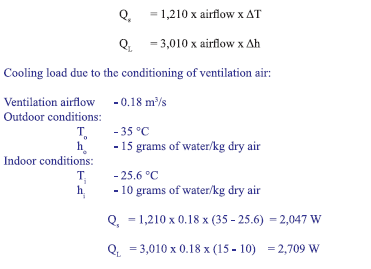
III. Cooling load due to ventilation
In addition to these space cooling loads, there are other loads that affect the cooling coil in the building HVAC system. These include the load of the outdoor air, deliberately brought into the building for ventilation purposes and heat generated by the fans in the system. These loads are added to the space load to determine the total cooling load for the building. Estimating these additional components is necessary to properly size the cooling coil for the system.
The amount of outdoor air required for a space is often prescribed by local building codes or industry standards. One such standard, ASHRAE Standard 62, Ventilation for Acceptable Air Quality, prescribes the quantity of outdoor air required per person (or per unit area) to provide adequate ventilation for various types of spaces.
'
In this example, calculating the required quantity of outdoor air involves multiplying the number of people in the space by the 0.01 m3/s of outdoor air required per person in an office space.
The sensible and latent loads from ventilation are calculated using the same equations as for infiltration:
IV. System heat gains
There may be other sources of heat gain within the HVAC system. One example is heat generated by
supply air fans. The heat gain from fans is associated with three energy conversion losses as given
below.
Fan motor heat gain = Power input to motor x (1-Motor efficiency)
Fan blade heat gain = Power input to fan x (1- Fan efficiency)
Duct heat gain = Power input to fan x Fan efficiency
The system heat gains are not considered in this example calculation
Summary of total coil cooling loads
Calculation of supply air
The proportions of sensible and latent heat must be known in order to determine the proper condition of the air supplied to cool the space. This Sensible Heat Ratio (SHR), is the ratio of sensible heat gain to total (sensible + latent) heat gain, and is defined as follows:
SHR = Sensible heat gain / (Sensible heat gain + Latent heat gain)
= 21623 W/ (21623 W + 2599 W)
= 0.89
This means in this example 89% of the cooling load for the space under consideration is sensible and
11% is latent.
Supply air flow = Sensible heat gain / {1210 x (Room dry bulb temp. — Supply dry bulb temp.)}
The next step is to either assume the supply air dry bulb temperature and calculate the supply air flow or assume the supply air flow and calculate the supply air temperature.
In this example assuming supply air dry bulb temperature as 12.8 °C
Supply air flow = 21623 W/{1210 x (25.6 °C — 12.8 °C)}
=1.4m3/s
Performance Assessment of Lighting System
Lighting accounts for a significant portion of the energy use in commercial buildings. In addition, heat generated by lighting contributes to the thermal load to be removed by the cooling equipment. The details of the lighting source which include the wattage, type of lamp and inventory of lamp needs to be collected floor wise or section wise and lighting power density (LPD) is to be determined.
Lighting Power Density (LPD): It is defined as the ratio of total operating lighting load (W) for a specified region of the building to the built up area (m7) of that specified region. LPD for a typical building is assessed and given in the table 14.2.
Table 14.2 Determination of lighting power density (LPD)
Methodology of Lighting System Assessment:
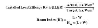
Calculation of Installed Load Efficacy Ratio (TILER):
Where, L = length of interior; W = width of interior; Hm = the mounting height, which is the height
of the lighting fittings above the horizontal working plane.
Determination of Measurement Points
The number points in which the lux level measurements are to be made depends on room index. The table 14.3 gives the minimum number of measurement points for a given room index.
Table 14.3 Number of lux measurement points
The average maintained illuminance is obtained by averaging the lux readings taken at different measurement points in a room or floor. The target lux/W/m/ for maintained illuminance on horizontal plane is given in table 14.4.
Table 14.4 Target lux/W/m2 values for maintained illuminance on horizontal plane for all room indices and applications
The installed load efficacy ratio is the ratio of actual calculated lux/W/m2 to the target lux/W/m2 given
in the table 14.5.
Table 14.5: ILER Calculation Procedure:
Referring to Table 14.6, ILER of 0.7 means that there is a scope for review of the lighting system.
Table 14.6 Assessment (Indicators of Performance)

Having calculated the ILER for an existing lighting installation, then the difference between the
actual ILER and the best possible (1.0) can be used to estimate the energy wastage.
Annual Energy Wastage : (1 — ILER) x (Watts / 1000) x operating hours per annum
: (1 — 0.7) x (990 / 1000) x 8 hrs/day x 300 days
: 712 .8kWh/ annum
Inference: ILER Ratios of 0.75 or more may be considered to be satisfactory. Existing installations with ratios of 0.51 - 0.74 certainly merit investigation to see if improvements are possible. Of course there can be good reasons for a low ratio, such as having to use lower efficacy lamps or less efficient luminaire in order to achieve the required lighting result — but it is essential to check whether there is a scope for a more efficient alternative. Existing installations with an ILER of 0.5 or less certainly justify close inspection to identify options for converting the installation to use more efficient lighting equipment.
This process of comparing the installed load efficacy (ILE) with the target value for the Room Index
and type of application can also be used to assess the efficiency of designs for new or replacement
of general lighting installations. If, when doing so, the calculated ILE (lux/W/m?) is less than the
target value then it is advisable to ascertain the reasons. It may be that the requirements dictate a
type of luminaire that is not as efficient as the best, or the surface reflectance are less than the normal
maxima, or the environment is dirty, etc. Whatever the reasons, they should be checked to see if a
more efficient solution is possible.
Solved Example:
Determine the cooling load of a commercial building for the following given data:
Outdoor conditions : DBT = 35°C, WBT = 25°C, Humidity = 18 g of water / kg of dry air
Desired indoor conditions : DBT = 25.6°C, RH = 50 %, Humidity = 10 g of water / kg of dry air
Total area of wall = 40 m’, Total area of window = 20 m?
U— Factor ( Wall ) = 0.33 W/mK
U — Factor ( Roof ) = 0.323 W/m?K
U — factor [ fixed windows with aluminium frames and a thermal break ] = 3.56 W /m2K
Other data:
¢ 15 mx 25 mroof constructed of 100 mm concrete with 90 mm insulation & steel decking.
¢ CLTD at 17:00 hr : Details : Wall = 12°C; Roof = 44°C; Glass Window = 7°C
e SCL at 17:00 hr : Details : Glass Window = 605 W/ m2
¢ Shading coefficient of Window = 0.74
¢ Space is occupied from 8:00 to 17:00 hr by 25 people doing moderately active work.
¢ Sensible heat gain / person = 75 W; Latent heat gain / person = 55 W; CLF for people = 0.9
¢ Fluorescent light in space = 21.5 W/m2; CLF for lighting = 0.9
¢ Ballast factor details = 1.2 for fluorescent lights & 1.0 for incandescent lights
¢ Computers and office equipment in space produces 5.4 W/m2 of sensible heat
¢ One coffee maker produces 1050 W of sensible heat and 450 W of latent heat
e Air changes / hr of infiltration = 0.3
¢ Height of building = 3.6 m
Solution:
I. External Heat Gain
(i) Conduction heat gain through the wall = U — factor x net area of wall x CLTD
0.33 x (40-20) x 12 ]=79.2 W
(ii) Conduction heat gain through the roof =U — factor x net area of roof x CLTD
= 0.323 x (15 x 25) x 44
= 5 329.5 W
(111) Conduction heat gain through the windows
= U-factor x net area of windows x CLTD
= (3.56 x 20 x 7) = 498.4 W
(iv) Solar radiation through glass = Surface area x Shading coefficient x SCL
= (20 x 0.74 x 605) = 8954 W
II. Internal Heat Gain
(1) Heat gain from people = Sensible heat gain + Latent heat gain
Sensible heat gain = (No. of people x Sensible heat gain / person x CLF)
= (25 x 75 x 0.9) = 1687.5 W
Latent heat gain = No. of people x Latent heat gain / person
= (25 x 55) = 1375 W
Therefore, Heat gain from people = (1687.5 + 1375) = 3062.5 W
(11) Heat gain from lighting = (Energy input x Ballast factor x CLF)
Energy input = (Amount of lighting in space/unit area) x Floor area
= 21.5 x (15 x 25) = 8062.5 W
Therefore, heat gain from lighting = (8062.5 x 1.2 x 0.9) = 8707.5 W
(iii) Heat generated by equipment:
Sensible heat generated by coffee maker = 1050 W
Latent heat generated by coffee maker = 450 W
Sensible heat gain by computers and office equipment =5.4x 375 = 2025 W
Therefore, Heat generated by equipment = 3525 W
(iv) Heat gain through air infiltration = (Sensible heat gain + Latent heat gain)
Sensible heat gain = (1210 x airflow x AT)
Airflow = (Volume of space x air change rate) / 3600
= {(15 x 25 x 3.6) x 0.3} / 3600
= 0.1125 m?/s
Therefore, sensible heat gain = 1210 x 0.1125 x (35 — 25.6) =1279.58 W
Latent heat gain = 3010 x 0.11x 25 (18-10) =2709W
--------------------------


Comments