GENERAL_ASPECTS_OF_ENERGY_MANAGEMENT_AND_ENERGY_AUDIT
(CHAPTER 11:NEW AND RENEWABLE ENERGY SOURCES (NRES))
Concept of New and Renewable Energy
Renewable energy is energy obtained from sources that are essentially inexhaustible such as sun and wind. Examples of renewable resources include wind power, solar power, geothermal energy, tidal power, bio- energy (bio-fuels grown sustainably) and hydropower. A renewable energy system converts the energy found in sunlight, wind, falling-water, sea-waves, geothermal heat, or biomass into a form, we can use such as heat or electricity. Another important feature of renewable energy is that it can be used without the release of harmful pollutants. Renewable energy is also known as non-conventional energy. Renewable energy sources are essentially flows of energy unlike the fossil and nuclear fuels which are considered stocks of energy.
Fundamentals of Solar Energy
Solar radiation is radiant energy emitted by the sun comprising of ultra-violet, visible and infra-red radiation. The amount of solar radiation that reaches any given location is dependent on several factors including the geographic location, time of day, season, landscape, and local weather. Because the earth is round, the sun strikes the surface at different angles ranging from 0° (just above the horizon) to 90° (directly overhead). When the sun’s rays are vertical, the earth’s surface gets maximum energy possible. The more slanted the sun’s rays are, the longer they travel through the atmosphere, becoming more scattered and diffuse.
Solar Constant
Solar constant is the rate at which solar energy, at all wavelengths, is received per unit area at the top level of Earth’s atmosphere. The solar constant actually varies by about 0.3% over the 11-year solar cycle but averages about 1,368 W/m’. Each planet has its own planetary solar constant.
Solar Insolation
Solar Insolation is the amount of solar energy that strikes a square metre of the earth’s surface in a single day. Insolation is greatest when the surface is normal to the Sun. As the angle increases beyond a direction normal to the surface and the sunlight, the insolation is reduced in proportion to the cosine of the angle. The average incoming radiation is known as solar insolation and is one-fourth the solar constant, or 342 W/2.
By knowing the insolation levels of a particular area, required size of solar collector and energy output can be calculated. An area with poor insolation levels will need a larger collector than an area with high insolation levels. The values are generally expressed in kWh/m/7/day. India receives solar energy in the region of 5 to 7 kWh/m? for 300 to 330 days in a year. This energy is sufficient to set up 20 MW solar power plant per square kilometre land area.
Solar energy can be used through two different routes, namely, Solar Thermal Energy and Solar electric (Solar Photovoltaic) Energy. Solar thermal systems uses the sun’s heat and convert it into heat energy while solar photovoltaic systems uses sun’s heat to produce electricity.
Solar Thermal Energy
Solar collectors are the main component of most of solar energy systems. The collector absorbs the sun’s energy and converts it into heat energy. This energy is then transferred to a fluid or air which is used to heat water, generate electricity, dry materials, distill water or cook food. When used for heating purpose, solar thermal system can partially or fully replace the conventional fuels such as coal, oil and electricity.
Various applications of solar thermal energy discussed are
¢ Solar Water Heating System (Flat-plate collector & Evacuated tube collector)
¢ Solar Thermal Power Systems (Power tower,parabolic trough collector)
Solar Water Heating System
A solar water heating system (Figure 11.1) consists of a flat plate or evacuated tube solar collector, a storage tank and connecting pipes. The system is generally installed on the roof or on open ground, with the collector facing the sun and connected to a continuous water supply. The collectors are generally mounted on a north-facing roof (in southern hemisphere). Water stored in the tank remains hot overnight . as the storage tank is insulated and heat losses are small.
Figure 11.1 Solar Water Heating System
Solar Flat Plate Collector
The most common collector is called a flat-plate collector. Flat-plate collectors heat the circulating fluid to a temperature of about 40-60°C. Flat plate collector is highly dependent upon ambient temperatures. It has good efficiency if ambient temperature is high. Consequently, heat output is higher during summer months than winter months in a flat plate collector.
The flat plate collector (Figure 11.2) usually comprises of copper tubes welded to copper sheets (both coated with a highly absorbing black coatings) with toughened glass sheet on top for cover and insulating material at the bottom. The entire assembly is placed in a flat box.

Evacuated Tube Collector
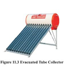
For higher temperatures, evacuated tube collectors are used. Evacuated tube collector is less dependent upon ambient temperature unlike flat plate collector and its efficiency does not drop with ambient temperature. In this type of solar collector, evacuated glass tubes are used instead of copper in which case a separate cover sheet and insulating box are not required. Water flows through the tubes, absorbs solar heat and is stored in a tank. This type of solar collector can reach high temperatures upto 150°C.
Evacuated tube collector is shown in Figure 11.3.

Evacuated tube collector comprises of two concentric glass tubes fused in the ends as shown in Figure 11.4. The air is evacuated from the gap between the tubes.
The evacuated double-walled glass tube provides thermal insulation similar to that of thermally insulated “Thermos” bottle. The outer glass tube is clear, and the surface of the inner glass tube is coated with a special heat material that absorbs the sun’s energy.
Sun rays penetrate the outer clear glass and heat energy is absorbed by the inner coated glass. The vacuum permits the heat radiation to enter the outer tube. The absorbent coating on the inner tube converts short wave radiation to long wave radiation thus preventing re-radiation to atmosphere. Since conduction cannot take place in vacuum, heat loss due to conduction back to atmosphere is also prevented. Because of this principle, more heat is trapped compared to a flat plate collector. The heat
loss in Evacuated tube collector is less than 10% compared with 40% for a flat plate collector. Water
flows in through a third, innermost concentric feeder tube and hot water flows out in the annulus outside the feeder tube in contact with the absorber tube surface.
Solar Electrical Energy
There are broadly two ways of generating electrical energy from solar power; the thermal route and direct conversion route through photovoltaic. There are two basic types of solar thermal power stations: power tower and parabolic trough collector.
Power Towers
A typical power tower (see Figure 11.5) operation is described as follows:
1. Sunlight is concentrated and directed from a large field of heliostats (mirrors) to a receiver on a tall tower.
2. Molten salt (for example liquid sodium) from the cold salt tank is pumped through the central receiver where it is heated to 566°C).
3. The heated salt from the receiver is stored in the hot salt thermal storage tank.
4. Molten salt is pumped from the hot salt tank through a steam generator that creates steam,
which drives a steam turbine, generating electricity.
5. Cold salt at 288°C flows back to the cold salt thermal storage tank and is re-used.
Parabolic Trough Collector
Parabolic Trough Collector is currently the most proven solar thermal electric technology. This system uses a Series of specially designed parabolic curved, trough shaped reflectors that focus the sun’s energy onto a receiver tube running at the focus of the reflector as shown in Figure 11.6. Because of their parabolic shape, troughs can focus the sun at 30-60 times its normal intensity on the receiver pipe. Heat transfer fluid (such as water) in the receiver is heated to a temperature of about 400°C. Large arrays of these collectors are coupled to provide high temperature water for driving a steam turbine. The collectors are aligned on an east-west axis and the troughs are rotated to follow the sun to
maximize the sun’s energy input to the receiver tube. Such power stations can produce many megawatts (MW) of electricity, but are confined to areas where there is sufficient solar insolation.
Solar Photovoltaic Technology
Direct conversion of solar energy to electricity takes place through photoelectric effect. The photoelectric or photovoltaic effect is the process in which the two dissimilar materials in close contact produce an electrical voltage when struck by light or radiant energy. Discrete packets of light energy known as photons, strike the Photovoltaic (PV) cell, knocking the electrons in the silicon material out of their normal energy state, putting them in a position to be conducted as electricity (Refer Figure 11.7).
The photoelectric effect only occurs when a photon which has the correct amount of energy strikes an atom in the solar cell. The amount of energy needed is dependent on the material the solar cellismadefrom.This means that the solar cell is not able to convert all the different wavelengths of light which are hitting it. Because of this,solar cells are “tuned” during their manufacturing to absorb the spectrum of sunlight that is most intense. This phenomenon is exploited to form the individual solar cells on wafers of silicon.Since Silicon is naturally reflective in nature, each photovoltaic cell is typically covered with an anti-reflective coating to minimize any loss from reflection.
PV panels comprise of PV cells. Solar cells are connected in series and parallel combinations to form modules that provide the required power. PV cells have been made with silicon (Si), gallium arsenide (GaAs), copper indium diselenide (CIS), cadmium telluride (CdTe), and a few other materials.
A Photovoltaic (PV) module comprise of PV panels (also known as solar panels), battery system, charge controller, inverter as shown in Figure 11.8.
One silicon cell generally produces 0.5 Volts. 36 such cells connected together are called a PV module and it has enough voltage to charge 12 V battery and run pump and motor. Modules can be connected together to form an array and generate more power.
The wattage output of a PV module is rated in terms of peak Watt (Wp). The peak Watt output power from a module is defined as the maximum power output that the module could deliver under standard test conditions. Single PV module can be manufactured with capacity ranging from 5 Wp to 120 Wp.
Stand-alone SPV Power Plant: These systems are used where conventional grid supply is not available, or is irregular. In an SPV power plant, electricity is centrally generated and made available to users through a local grid in a ‘stand-alone mode’. The most common use for such plants is the electrification of remote villages, power for hospitals, hotels, communication equipment, railway stations, border outposts etc.
Grid connected Solar System: Grid connected solar system (Figure 11.9) use an inverter that synchronizes with the utility power. These systems do not generally require batteries, although batteries can be used to provide backup power if the utility power goes out. Grid connected solar is easier to install and maintain than stand-alone system.
Building-integrated PV Systems: In building-integrated photovoltaic (BIPV) system, PV panels are integrated into the roof or facade of a building as shown in Figure 11.10. BIPV provides photovoltaic power as well as weather proofing and glazing of buildings. SPV panels generate electricity during the daytime, which is used to meet a part of the electrical energy needs of the building. Since PV cells are integrated into the buildings, no separate costly mountings are required.
Wind Energy
The use of wind energy is not new and has been used for thousand of years for applications such as water pumping, milling grains, mechanical power, sailing etc. However, it is the use of wind energy for electricity generation that is receiving most attention today. Modern windmills are normally called as wind turbines as their functions are similar to gas and steam turbines. They are also called as wind energy conversion systems (WECS), and those used to generate electricity are described as wind generators.
How Wind is Created?
As the earth orbits the sun daily, it receives light and heat. The majority of the heat from the sun is received North Pole at the equator and it gradually reduces towards both Gold Cold poles. Across the earth these heat differences help create wind. In warmer regions of the earth the air is hot and is therefore at a high pressure, compared to colder regions, where the air is at a low pressure. Wind is the
movement of air from area’s of high pressure to low pressure. Ideally, wind should flow from equator to the direction of either pole if earth is not rotating.
However, rotation of earth creates a force known as Coriolis force. The Coriolis force is swirling action on the winds because of earth rotation. This causes series of wind circulations in both northern and southern latitude as shown in Figure 11.11.
The local winds are largely affected by earth terrain. The earth has large flat plains (desert regions), areas covered with plant life (rainforests), very uneven regions (mountain ranges) and very smooth regions (seas and oceans), all of which affect the wind near the surface of the earth to varying levels. Sea breeze is set up when hot air rises from land, which is heated faster than sea, rises into the sky where it cools off. High in the sky, the cooled air now moves towards the sea and sinks pressing cold air from sea towards land.
Variability in Wind Speed and its Effect
Wind speed and direction are continuously fluctuating. The wind will vary over few hours with weather system. Generally, tropics have steady moderate winds all year, temperate latitudes have much more variation in wind speed and in particular more high wind speed occurrences. Sites with more wind speed will generate more power. The Table 11.1 gives a guideline of different wind speeds and their potential in producing electricity.
Description of Wind Energy Technology
The most common type is horizontal-axis machines. Horizontal-axis wind turbines have the main rotor shaft and electrical generator at the top of a tower, and must be pointed into the wind.Blades on rotor of horizontal-axis machines can be in the front (upwind) or behind (downwind) of the tower.
Components of wind turbine system
The various components of a wind turbine system are shown in the Figure 11.12 and detailed description is given as follows:
Rotor: The shape of rotor blade and angle in relation to the relative wind direction affect the aerodynamic performance of the blades. Rotors can be single bladed, twobladed or three-bladed. Multi-bladed rotors are also available. Two- and three-bladed rotors are commonly used for power generation. The three-bladed rotors operate more smoothly and generally more quietly than two-bladed rotors. Multi-bladed rotors have large starting torque in light winds and are used for water pumping and low frequency mechanical power.
Nacelle Assembly: Nacelle is the part of wind turbine at top of tower housing containing gear box, generator assemblies and any control component. The main components of Nacelle assembly are shown in Figure 11.13.

Low-speed shaft: The low-speed shaft, which is the main shaft, is connected directly to the rotor hub.
The rotor turns the low-speed shaft at about 30 to 60 rotations per minute.
High-speed shaft: The high-speed shaft is connected to the low-speed shaft by the gear box and drives
the generator. The high-speed shaft will turn at between 1,000 and 1,800 rpm.
Gear box: Gears connect the low-speed shaft to the high-speed shaft and increase the rotational speeds
from about 30 to 60 rotations per minute (rpm) to about 1,000 to 1,800 rpm, which is the rotational
speed required by most generators to produce electricity.
Generator: The generator converts the turning motion of wind turbines blades into electricity. For
commercial applications, the most common type of generator is an induction generator that produces
50-cycle AC electricity.
Disc Brake: The disc brake is located on main shaft before the gear box or on high speed shaft after
the gear box. The basic purpose is to slow down the rotor.
Yaw Control: It is necessary for rotor axis to be aligned with wind direction in order to extract as much of wind kinetic energy as possible. Large wind turbines with upwind rotors require yaw control to align the rotor with the wind. To enable this, any change in wind direction, sensors activate the yaw
control motor, which rotates the nacelle and rotor assembly until turbine 1s properly aligned.
Operating Characteristics of Wind Turbine
A few of the important operating characteristics of a wind turbine include the cut-in speed, rated speed,
cut-out speeds, power output and capacity factor. Refer Figure 11.14.
Cut-in Speed: There is a minimum speed at which a wind turbine can reliably produce useable power.
This is known as the cut-in speed which is generally around 5 m/s.
Rated Speed: Most wind turbines are designed to generate maximum power at a fixed wind speed. This is known as rated power and the minimum wind speed at which it is achieved is the rated wind speed. The rated wind speed is chosen to fit the local site and wind regime and 1s often 1.5 times the site mean wind speed.
Cut-out Speed (Furling Speed): Above a certain speed beyond the rated speed, the wind turbine will need to shut down and stop operation to prevent damage to the unit. Cut-out speeds vary by manufacturer from about 20 to 30 m/s. The wind speed at which shut down occurs is called the cut-out speed. Cutout speed is also known as furling speed.
Betz Limit: It is impossible for the blades of a wind turbine to be 100% efficient since some of the wind energy must pass through the blades to make the turbine turn. Air flowing over the blades and through the rotor area makes a wind turbine function. The wind turbine extracts energy by slowing down the wind. The theoretical maximum amount of energy in the wind that can be collected by a wind turbines rotor is approximately 59%. This value is known as the Betz limit. Considering the Betz limit and the efficiency losses through the generator, gearbox, etc, will result in only about 15-25% of
the wind energy being converted into useful power.
Rotor Efficiency: The ability of a turbine rotor to extract the wind’s power depends upon its “efficiency”.
Thus to express the power output of the turbine, a non-dimensional coefficient of performance of the
blades (Cp) is included. The coefficient of performance of blades (Cp) varies with speed and generally varies between 0.33 -0.59.
Power Available from the wind turbine: Power extracted by wind turbine is proportional to the cross
sectional area of the wind intercepted by wind turbine and cube of the wind speed.
The power generated by a wind turbine can be found using the following formula:

Power generated is highly dependent upon wind speed. Doubling the wind speed increases the power
by eight times, but doubling the turbine area only doubles the power. Thus optimizing the siting of
wind turbines in the highest wind speed areas has significant benefit and critical for the best economic
performance.
For example, consider a wind turbine with 6 m diameter rotor, a coefficient of performance of 0.30,
generator efficiency of 0.8, a gearbox efficiency of 0.90, and a wind speed of 11 m/s.
What is the expected power output in watts?
P=0.5 * 1.2 * 3.14/4 * 6? * 0.30 * 0.8 * 0.9 * 11^3
P = 4875 watts, or 4.875 kW
Capacity Factor: The capacity factor of a wind turbine is the actual energy output of a wind turbine
during a given time period, usually one year, compared to its theoretical maximum energy output.
The capacity factor (CF) is,
CF = kWh produced / (8760 * Nameplate rating of the wind turbine, kW)
Typical capacity factors are 20-40% with values at the upper end of the range in particularly favorable
sites.
A 2.5 MW wind turbine could produce theoretical maximum of 21,900,000 kWh’s per year
(2.5 * 1,000 *8760).
However, due to the variability of the wind the unit has actually produced 5,000,000 kWh per year.
In this example, the capacity factor is,
CF = 5,000,000 / (2.5 * 1,000 *8760)
CF = 22.8%
Biomass Energy
Biomass is basically organic matter such as wood, straw, crops, algae, sewage sludge, animal waste and/or other biological waste. Bioenergy is the energy derived from biomass. In energy terms, biomass can be viewed as a form of stored solar energy. The sun’s energy is captured and stored (via photosynthesis) in the biomass material. The carbon dioxide released during the burning of biomass when used as fuel is largely balanced by the absorption/ capture of carbon dioxide during its growth. Hence it is considered ‘carbon neutral’ The different methods used to generate energy from biomass are:
Direct Combustion of Biomass
Biomass energy used to generate heat and electricity through direct combustion in modern devices, ranging from very small scale domestic boiler to multi megawatt size power plant electricity. Direct combustion is the combustion of biomass in a grate, stoker or fluidized bed with excess air followed by capturing the release of energy, which can then be used to provide steam or hot water for process heating and/or for providing electricity. Solid biomasses include coconut shells, rice husks, bagasse, wood waste, oil seed cakes such as de-oiled bran (DOB) etc. Biomasses of low bulk density are processed into pellets or briquettes. A typical pelleted fuel is shown in Figure 11.15

Gasification of Biomass
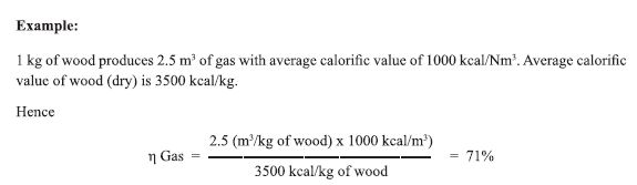
Biomass contains carbon, hydrogen and oxygen molecules. Complete combustion would produce carbon dioxide (CO,) and water vapour (H,O) whereas combustion under controlled conditions 1.¢e. partial combustion produces carbon monoxide (CO) and hydrogen (H,), which are combustible gases. The biogas produced through gasification is called as producer gas. The producer
gas has relatively low calorific value, ranging from 1000 to 1200 kcal / Nm>. The conversion efficiency
of the gasification process is the range of 60-70%. It can be used for combustion in a reciprocating
engine. When gas is used in dual fuel DG set, it can result in 65-85% diesel savings.
Gasification is a partial combustion of biomass and takes place at temperature of about 1000°C. Partial
combustion is facilitated by supplying air less than stoichiometric requirements. The products of
combustion are combustible gases like Carbon monoxide (CO), Hydrogen (H,) and traces of Methane
(CH,) and non useful products like tar and dust. The production of these gases is by reaction of water
vapor and carbon dioxide through a glowing layer of charcoal. Thus, the key to gasifier design is to
create conditions such that (a) biomass is reduced to charcoal and, (b) charcoal is converted at suitable
temperature to produce CO and H.,.
1. gasification system consists of four main stages:
2. Feeding of feedstock
3.Gasifier reactions where gasification takes place
4. Cleaning of resultant gas Drying Zone
5. Utilization of cleaned gas.
Biomass gasifier (Figure 11.16) is a thermo chemical converter / reactor where various physical and chemical reactions take place. Biomass is passed through various zones — Drying/ Distillation Zone,Pyrolysis Zone, Combustion Zone & Reduction Zone. When the biomass is passed through all the above zones, it gets converted into a high quality combustible gas called Producer Gas.


Spark ignition engines running on producer gas on an average produces 0.55-0.75 kWh of energy from
1 kg of biomass. Compression ignition (diesel) engines cannot run completely on producer gas. Thus
to produce 1 kWh of energy they consume kg of biomass and 0.07 litres of diesel. Consequently
they effect 80-85% diesel saving.
Biomethanation of Biomass (Anaerobic Process)
Biomass can also be converted into bio-methane gas which is composed mainly of methane and carbon
dioxide. The process is based on biological digestion / anaerobic digestion (biomethanation) of biomass.
This is the only process giving additional advantage of high grade manure as the by-product. The raw materials for biomethanation process include manure, sewage sludge, municipal solid waste, fruit and vegetable waste, food waste, distillery wastes and other biodegradable wastes. Bio-methane can completely replace natural gas for applications using natural gas such as boilers, furnaces, IC engines etc.
Biomass offers higher energy efficiency through form of biogas than by direct burning (refer chart). Biogas produced through anaerobic process (in the absence of air) using cow dung as input material is generally called as Gobar gas. The gobar gas is a gas mixture typically comprising of around 60% methane and 40% carbon dioxide that is formed when organic matter such as dung, industrial organic wastes,vegetable wastes etc. are broken down by specific bacteria in the absence of air, at slightly elevated
temperatures (most optimum between 35 - 40°C). The biogas process is also known as anaerobic digestion or fermentation, and provides a clean fuel that can be produced on a scale varying from a small household system to a large commercial plant of several thousand cubic metres. Biogas can be used for electricity generation or purified to be used as a vehicle fuel.
Anaerobic digestion is a four-stage process as specific bacteria feed on certain organic materials. In the first stage, acidic bacteria dismantle the complex organic molecules into smaller molecules and in the second stage, these molecules further breakdown into organic acids, carbon dioxide and ammonia. A second type of bacteria (methanogenic bacteria) starts to convert these molecules into acetates and hydrogen in the third stage, which then converts to methane in the fourth stage. These methane producing bacteria are particularly influenced by the ambient conditions, which can slow or halt the process completely if conditions are not favourable.
A typical biogas plant using floating drum biogas prevalent in India is described in Figure 11.17. This design consists of a tank or a well with a partition wall to prevent mixing of influent fresh dung slurry with the outgoing spent slurry. The gas produced is trapped under a plastic or a metallic drum. With the continuous production more gas is trapped under this bell and the drum rises. This acts as a gas storage unit and when the tap above is released, the gas is discharged at more or less constant pressure. A non-return valve in the outlet is a valuable investment to prevent air being drawn into the digester, which would destroy the activity of the bacteria and provide a potentially explosive mixture inside the drum.

Biofuels from Biomass
Biomass can be converted into liquid fuels such as Ethanol and Biodiesel to partially replace the conventional petroleum fuels.
Ethanol is commonly produced by the fermentation of molasses, a by-product in sugar manufacture. It is also produced by fermenting any biomass feedstock rich in carbohydrates (starch, sugar or cellulose). e.g.: Sugar beet, Sweet corn and Ligno-cellulosic materials (straw and wood waste), which
are much cheaper than molasses, are now being considered for manufacturing ethanol. Ethanol is used
as a fuel additive to cut down vehicle’s carbon monoxide and other smog causing emissions. Flexible
fuel vehicles, which run on mixture of gasoline, use up to 85% ethanol.
Biodiesel is a good alternative for diesel. The most economical way of producing biodiesel is by transesterification of extracted oil (e.g. Jatropha seeds oil) with alcohol such as methanol. Jatropha is anon edible tree-borne oilseed which grows in dry and arid land. Biodiesel can be used as an additive
to reduce vehicle emissions (typically 20%) or in its pure form as a renewable alternative fuel for diesel engines. All oils extracted from plant origin, waste cooking oil and animal fat can be used as raw materials for biodiesel production. The biodiesel cycle is shown in Figure 11.18.
Hydro Power
Water power can be harnessed in many ways; the most common way is to use a turbine which is turned
by water moving in a controlled manner. Large dams hold water which can be used to provide energy for industry and grid electrification systems. Smaller systems can provide energy to remote regions without the need to build dams. Classification of hydro by size is given in the Table 11.2.

Micro-hydro power is the small-scale harnessing of energy from falling water; for example, harnessing enough water from a local river to power a small factory or village. The Figure 11.19 shows the main components and layout of a run-of-the-river micro-hydro scheme. This type of scheme requires no water storage but instead diverts some of the water from the river which is channelled along the side of a valley before being ‘dropped’ into the turbine via a penstock.

Water into Watts
To determine the power potential of the water flowing in a river or stream it is necessary to determine
both the flow rate of the water and the head through which the water can be made to fall. The potential
power can be calculated as follows:
Small water turbines rarely have efficiencies better than 80%. Power will also be lost in the pipe carrying the water to the turbine, due to frictional losses. A rough guide used for small systems of a few kW rating is to take the overall efficiency as approximately 50%. Thus, the theoretical power must
be multiplied by 0.50 for a more realistic figure.
Example: A turbine generator set operating at a head of 10 metres with flow of 0.3 cubic metres per second will deliver approximately, (9.81 x 0.5 x 0.3 x 10 =) 14.715 kiloWatts of electricity.

Fuel Cell
Input to a Fuel Cell is hydrogen. Hydrogen combines with oxygen to produce electricity through an electrochemical process with water and heat as by-products. Since conversion of the fuel to energy takes place using an electrochemical process (not combustion process), fuel cell is a clean, quiet and highly efficient process. Although there are many types of fuel cells, the principle of operation is similar.
Operation of Fuel Cell
A Fuel Cell (Figure 11.20) consists of two catalyst coated electrodes surrounding an electrolyte. One electrode is an anode and the other is a cathode. The process begins when hydrogen molecules enter the anode. The catalyst coating separates hydrogen’s negatively charged electrons from the positively charged protons. The electrolyte allows the protons to pass through to the cathode, but not the electrons.
Instead the electrons are directed through an external circuit which creates electrical current. While the electrons pass through the external circuit, oxygen molecules pass through the cathode. The oxygen and the protons combine with the electrons after they have passed through the external circuit producing water and heat.

Individual fuel cells can then be placed in a series to form a fuel cell stack. The stack can be used in
a system to power a vehicle or to provide stationary power to a building.
In general all fuel cells have the same basic configuration - an electrolyte and two electrodes. Whatever be the type of fuel cell, all require hydrogen as fuel. Hydrogen is a secondary energy resource, meaning it must be made from another fuel. Hydrogen can be produced in a variety of ways such as steam reforming of natural gas, electrolysis of water, gasification of biomass, etc. The biggest hurdle to large scale commercial exploitation of fuel cell is the cost of production of hydrogen which is now very high.


Applications of Fuel Cells
The type of fuel cells used is decided by the application in which it is used. Since fuel cells are capable
of producing power anywhere in the | Watt to 10 Megawatt range, they can be applied to almost any application that requires power.
The low power range fuel cells can be used as source of power for personal electronics applications such as charging of cell phones, personal computers etc. The high power fuel cells (1 kW — 100 kW range) fuel cell can be used to power vehicles. The megawatt range fuel cells can be used to convert energy for distributed power uses. Application of fuel cells in the transportation sector has significant advantages like reduced complexity of design.
Energy from Wastes
Energy can be recovered from wastes (trash) via combustion of waste in incinerators and generating power. A typical Waste-to-Energy power plant using direct combustion is explained in Figure 11.21. Power generation from landfill gas Biogas produced from landfill is known as Landfill gas (Figure 11.22). This process is also an anaerobic digestion process as bacteria decompose organic matter naturally in absence of oxygen over time.
Landfill gas is composed mainly of methane and carbon dioxide. The methane gas produced in landfill
sites normally escapes into the atmosphere and contributes to greenhouse gas emissions. However, if
perforated pipes are inserted into the landfill, the landfill gas will travel through the pipes under natural
pressure to be used as energy source.
Wave Energy
Sea waves are the result of the concentration of energy from various natural sources like sun, wind, tides, ocean currents, moon, and earth rotation. Waves originate from wind and storms far out to sea and can travel long distances without significant energy loss, and hence power production is much steadier and more predictable. Unlike the wind and solar, power from sea waves continues to be produced round the clock.
Wave energy contains roughly 1000 times the kinetic energy of wind. Hence it allows smaller devices to produce power. Wave energy varies as the square of wave height whereas wind power varies with the cube of air speed. Water being 850 times as dense as air results in much higher power produced from wave averaged over time. Theoretically it is possible to extract 40 MW of power per km of coast where there are gentle waves (say | m height) and 1000 MW per km of coast where the wave height is
5m.
Kinetic energy from waves can be used to power a turbine. As shown in the Figure 11.23, the wave rises into a chamber. The rising water forces the air out of the chamber. The moving air spins a turbine which can turn a generator. When the wave goes down, air flows through the turbine and back into the chamber through doors that are normally closed thus generating power even when wave is receding.

Tidal Energy
How tide is caused?
Tidal energy is another form of ocean energy. Tides are generated by the combination of the moon and sun’s gravitational forces. Greatest effects of tides are in spring when sun and moon combine forces. Bays and inlets amplify the tide. Cycles of low and high tides occur twice a day. When tides come into
the shore, they can be trapped in reservoirs behind dams. Then when the tide drops, the water behind the dam can be let out just like in a regular hydroelectric power plant. In order for the tidal energy to be practicable for energy production, the height difference needs to be atleast 5 m is needed. The principle of working of tidal energy is shown in Figure 11.24.

Geothermal Energy
The top most part of the earth is the crust. Below the crust of the earth is a layer called mantle. The top layer of the mantle is a hot liquid rock called magma (see Figure 11.25). The crust of the earth floats on this liquid magma mantle. When magma breaks through the surface of the earth in a volcano, it is called lava.

For every 100 meters you go below ground, the temperature of the rock increases about 3°C. So, at a depth of about 3000 metres below ground, the temperature of the rock would be hot enough to boil water. Deep under the surface, water sometimes makes its way close to the hot rock and turns into boiling hot water or into steam. The hot water can reach temperatures of more than 148°C. When this hot water comes up through a crack in the earth, it is known as hot spring.
Some of the areas have so much steam and hot water that it can be used to generate electricity. Holes are drilled into the ground and pipes lowered into the hot water. The hot steam or water comes up through these pipes from below ground. A geothermal power plant is like in a regular power plant except that no fuel is burned to heat water into steam. Different types of geothermal power plants are described as follows:
Dry Steam Power Plants
A dry steam power plant (Figure 11.26) draws steam from a hydrothermal production well and sends it to a turbine/generator. The steam turns the turbine to generate electricity and is then condensed and returned to the geothermal reservoir via an injection well.
Flash Steam Power (Figure 11.27) draws hot water from a hydrothermal production well to a flash tank where a drop In pressure “‘flashes”’ the hot water (182°C) to steam. The steam turns a turbine/generator that generates electricity. The steam is then condensed and along with the remaining hot water not flashed into steam is returned to the geothermal reservoir via an injection well.
Binary Cycle Power Plant
Binary Cycle Power Plants (Figure 11.28) operateon the lower-temperature waters, 107° to 182°C). These systems use two closed loops. Binary cycle pumps hot water from well to a heat exchanger where hot water is used to heat a working fluid, usually organic compound with low boiling point.
This working fluid is then vaporized in a heat exchanger and used to turn a turbine. The geothermal water and the working fluid are confined to separate closed loops. So there are no emissions into the air.
---------------------------


Comments